ZEUS MVD Clock and Control
Last update 10/10/2000
The MVD readout will be asynchronous. The clock and control system
provides interfaces between the ZEUS global first level trigger
(GFLT), the run control system, the analogue to digital converter
(ADC) crates and the HELIX readout chips.
Overall diagram showing all parts of the C+C
system.
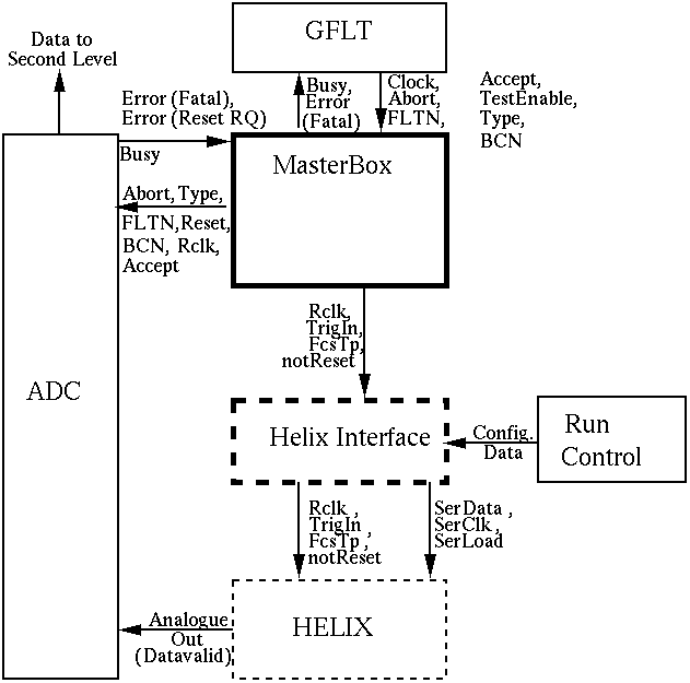
A schematic diagram of the
functionality of the clock and control system is given below:

Overview of ZEUS MVD Clock and Control. Full boxes are in the
rucksack (free standing electronics hall about 20m from the detector),
dashed boxes in the cryotower area, close to the detector. Boxes in
bold are considered part of the clock and control system. Key: Clock =
96ns HERA clock, Rclk = 96ns readout clock, FLTN = FLT number, Type =
trigger type, TrigIn = trigger input, FcsTp = test pulse command. BCN = Global bunch crossing number. The
names reflect those used in the Helix128S-2 User
Manual (Heidelberg)
The main functions of the clock and control are:
- Receive the clock from the GFLT during a run and distribute
appropriate clocks and GFLT information to the ADC and HELIX.
-
Receive trigger Accept, Abort signals and trigger information for the
event from the GFLT during a run and send them to the ADC.
- Send trigger input and trigger test pulse commands to the HELIX
chips on instruction from the GFLT. The clock and control must allow
for standalone (i.e. no GFLT) test runs.
-
Receive configuration data and instructions from the run control
system before a run and pass these to the HELIX chips via a three line
serial interface.
- Pass `busy' signal from the ADC to the GFLT.
- Receive `Error: Reset Request' signals from the ADC. The clock and
control should then send a busy to the GFLT on the next event. The
busy is held whilst the ADC crate performs error recovery. When this
is complete, the `Error: reset request' signal is reset and the clock
and control sends a `not reset' command to HELIX and removes the busy
signal to the GFLT.
Physically, the clock and control system will be divided into two
parts (indicated in the Figure). The `Masterbox' will sit in the
rucksack, along with the GFLT, the ADC crates and the run control
system. It will communicate with a `HELIX interface' which will be
positioned closer to the detector, in space which is available in the
ZEUS cryotower. Communication between the two will be via four electrical
signals. The HELIX interface will fan out to the HELIX chips on the MVD
via cables.
Masterbox
Overview
The Masterbox will consist of a single 9U board carrying out the
overall control tasks, communicating
via cables with one `slave' 9U board sitting in each ADC
crate. Communication between the ADC boards and the slaves will be via
the backplanes of these crates.
Original 1997 Proposal
Prototype System
Final System
HELIX Interface
The HELIX interface will consist of a VME crate containing 16 6U
`front end driver' boards, each performing the necessary functions and
fanning out to 16 readout cells. A readout cell consists of 8 HELIX
chips, and there are 256 readout cells in total. There are 144 (9
signals * 16 cells) twisted pair cables on each board
connecting to the readout cells on the detector.
There will be a further `patch panel' board receiving the four Masterbox
signals and distributing them to the 16 front end drivers.
Finally, the crate will contain a processor board which will monitor
for errors during the run, and before runs will receive
configuration data from the run control system and download it to
the HELIX chips via the front end drivers.
Further information
Estimated Costs
Estimates of costs have been made based upon previous experience with
ZEUS electronics and other projects. Combined with the resources
required for prototyping and testing which are detailed in the table
we therefore estimate the total cost of the project at £ 52,600.
In addition we will make use of an existing GFLT test box produced for
development and testing of the CTD readout, and a VME test crate at
UCL.
| Item | Estimated Cost
|
|
Masterbox | £ 5,000
|
|
Prototype/Spare Master | £ 5,000
|
|
Slaves (3 + spare) | £ 8,000
|
|
Optical links | £ 600
|
|
Front end drivers (16 + spares) | £ 20,000
|
|
Patch panel board (1 + spare) | £ 2,000
|
|
VME crate | £ 4,000
|
|
Processor | £ 4,000
|
|
Cabling and connectors | £ 4,000
|
|
Total | £ 52,600
|
Cost estimates for clock and control of ZEUS silicon
microvertex detector.

Contact
Jon Butterworth,
Dominic Hayes,
John Lane,
Gil Nixon,
Martin Postranecky
ZEUS MVD Electronics and DAQ


