Proton Calorimetry/Experimental Runs/2025/Trento 2025-03: Difference between revisions
| (63 intermediate revisions by 3 users not shown) | |||
| Line 1: | Line 1: | ||
== Beam Time Request Forms == | |||
https://www.hep.ucl.ac.uk/pbt/wikiData/BeamRequests/Trento_09_2025/ | |||
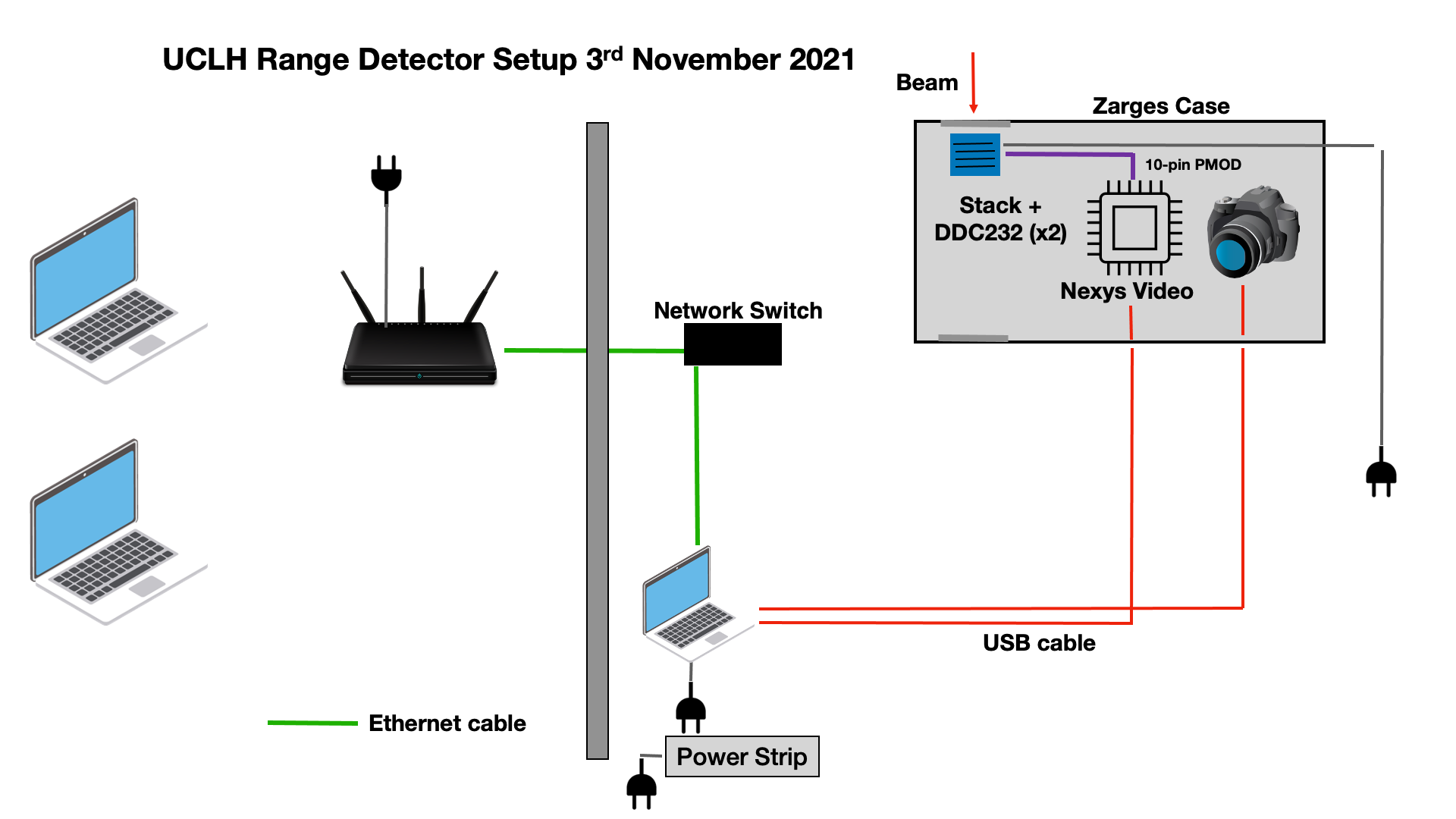
== Experiment Equipment == | == Experiment Equipment == | ||
{| class="wikitable" | {| class="wikitable" | ||
| Line 32: | Line 36: | ||
[http://www.hep.ucl.ac.uk/pbt/wikiData/images/UCLH_Nov2021/UCL_Setup.png http://www.hep.ucl.ac.uk/pbt/wikiData/images/UCLH_Jun2022/UCL_Setup.png] | [http://www.hep.ucl.ac.uk/pbt/wikiData/images/UCLH_Nov2021/UCL_Setup.png http://www.hep.ucl.ac.uk/pbt/wikiData/images/UCLH_Jun2022/UCL_Setup.png] | ||
</div> | </div> | ||
== Fiber Module Experiment Equipment == | |||
{| class="wikitable" | |||
! style="text-align: center;" | Item | |||
! style="text-align: center;" | Notes | |||
|- | |||
| style="text-align: center;" | 2D Fiber Arrays | |||
| style="text-align: center;" | 2 Modules of vertical and horizontal fibers | |||
|- | |||
| style="text-align: center;" | Read-out electronics | |||
| style="text-align: center;" | 2 Hamamatsu S13885-128 photodiode array each coupled to a Hamamatsu C9118-02 driver circuit | |||
|- | |||
| style="text-align: center;" | ZYBO Z7-10 Diligent FPGA development board. | |||
| style="text-align: center;" | To provide clocks to C9118. | |||
|- | |||
| style="text-align: center;" | NI USB-6366 Multifunction I/O device. | |||
| style="text-align: center;" | For interfacing between C9118 and PC. | |||
|- | |||
| style="text-align: center;" | DAQ laptop x1 | |||
| style="text-align: center;" | Control photodiode acquisition. | |||
|} | |||
== Experiment Plan == | == Experiment Plan == | ||
For each beam delivery, our acquisition time is 5 seconds. This gives us an optimal number of events. For FLASH beam time restrictions, we could consider reducing the acquisition time, if necessary. | |||
* Set up mains cabling and networking in treatment and control rooms. | * Set up mains cabling and networking in treatment and control rooms. | ||
** no beam | ** no beam | ||
| Line 55: | Line 82: | ||
*** 4 beam deliveries per energy | *** 4 beam deliveries per energy | ||
=== Setup === | |||
* Peli case set up on FLASH station. | |||
* Network connected through TIFPA experimental room patch panel: | |||
** Inside experimental room: | |||
*** Long cable from patch panel (1) to DLink switch. | |||
*** Long cable from switch to QuARC. | |||
*** Short cable from switch to profile monitor DAQ laptop. | |||
** Inside control room: | |||
*** Long cable from patch panel (5) to GL.iNet Slate router. | |||
*** Short cables to laptops. | |||
* Case aligned to room lasers: | |||
** Blocks used for levelling. | |||
** Set up on height adjustable platform. | |||
** Aligned to front cover plate. | |||
== Measurements 29/09/2025 == | |||
* Approximately 100 minutes running 29/09/2025 (20:50–22:30). | |||
* Peli case set up '''without''' movable stage: 1cm block under front, ~3mm under rear to level case. | |||
* Isocentre at upstream face of first stack (level with inner edge of wheel mounts). | |||
* Alignment checked with in room lasers after each adjustment. | |||
* Beam optics are '''different''' between CONV mode and FLASH mode: | |||
** Other than FLASH shoot through measurement with stack 1, running restricted to CONV mode. | |||
** Current sufficient at maximum ion source current to almost saturate QuARC). | |||
* SciFi monitor '''not''' installed. | |||
=== Calibration conventional and FLASH === | === Calibration conventional and FLASH === | ||
{| class="wikitable" | {| class="wikitable" | ||
!Run number | !Run number | ||
! | !Modules | ||
!Beam Energy (MeV) | !Beam Energy (MeV) | ||
!Estimated Range (mm) | !Estimated Range (mm) | ||
!Current (nA) | !Ion Source Current (nA) | ||
!Delivered protons | |||
!Irradiation time | |||
!Spot size (mm, FWHM) | !Spot size (mm, FWHM) | ||
!DDC232 FSR (pC) | !DDC232 FSR (pC) | ||
!DDC232 Integration Time (us) | !DDC232 Integration Time (us) | ||
!Acquisition Time (s) | |||
!Degrader WET (mm) | !Degrader WET (mm) | ||
!Beam setup | |||
!Comments | !Comments | ||
!Photodiode QB Fit | !Photodiode QB Fit | ||
!Replay Fit | !Replay Fit | ||
|- | |- | ||
| | |1 || 1, 2, 3 || Background || || 0 || 0 || 0 || N/A || 12.5 || 220 || 3 || 0 || Background || Lid open || || | ||
|- | |- | ||
| | |2 || 1 || Background || N/A || 0 || 0 || 0 || N/A || 12.5 || 170 || 3 || 0 || Background || Lid open || || | ||
|- | |- | ||
| | |3 || 1 || Background || N/A || 0 || 0 || 0 || N/A || 12.5 || 170 || 3 || 0 || Background || Lid open, added network switch to DAQ chain || || | ||
|- | |- | ||
| | |4 || 1 || Background || N/A || 0 || 0 || 0 || N/A || 12.5 || 170 || 3 || 0 || Background || Lid closed, BG with lid open ~0.10pC per PD, lid closed ~0.014pC || || | ||
|- | |- | ||
| | |5 || 1 || Background || N/A || 0 || 0 || 0 || N/A || 12.5 || 170 || 3 || 0 || Background || Lid open, Added long network cable between switch and wall patch panel || || | ||
|- | |- | ||
| | |6 || 1 || Background || N/A || 0 || 0 || 0 || N/A || 12.5 || 170 || 3 || 0 || Background || Lid closed, Peli case moved to FLASH beamline station and aligned with lasers @15.13 || || | ||
|- | |- | ||
| | |7 || 1 || Background || N/A || 0 || 0 || 0 || N/A || 12.5 || 170 || 5 || 50 || Background || Peli case aligned, cover plates removed, 50mm WET installed || || | ||
|- | |- | ||
| | |8 || 1 || 228 || 325 || - || - || - || 6.8 || 12.5 || 170 || 5 || 50 || FLASH, low current, shoot through front || Only 50% of measurements acquired, saturating; aiming for 1nA at detector || || | ||
|- | |- | ||
| | |9 || 1 || 228 || 325 || - || - || - || 6.8 || 12.5 || 170 || 5 || 50 || FLASH, low current, shoot through front || 4 sheets saturating; aiming for 0.5nA at detector || || | ||
|- | |- | ||
| | |10 || 1 || 228 || 325 || - || - || - || 6.8 || 12.5 || 170 || 5 || 50 || FLASH, low current, shoot through front || Sheets saturating; aiming for 0.5nA at detector; switching to CONV optics || || | ||
|- | |- | ||
| | |11 || 1 || 228 || 325 || 10 || 4E9 || - || 6.8 || 12.5 || 170 || 5 || 50 || CONV, high current, shoot through front || Switch to CONV mode, good FSR || || | ||
|- | |- | ||
| | |12 || 1 || 228 || 325 || 20 || - || - || 6.8 || 350 || 170 || 5 || 50 || CONV, high current, shoot through front || ~20nA isocentre, ~120pC per sheet maximum || || | ||
|- | |- | ||
| | |13 || 1 || 228 || 325 || - || 3E12 || - || 6.8 || 350 || 170 || 3 || 50 || CONV, high current, shoot through front || ~50nA isocentre, ~270pC per sheet maximum, Raspberry Pi frozen, restarted: only ~58% measurements recorded || || | ||
|- | |- | ||
| | |14 || 1 || Background || N/A || 0 || 0 || 0 || N/A || 12.5 || 170 || 3 || 50 || Background || Lid closed, stack rotated || || | ||
|- | |- | ||
| | |15 || 1 || 228 || 325 || 10 || 4E9(?) || - || 6.8 || 12.5 || 170 || 5 || 50 || CONV, shoot through back || ~1nA isocentre(?) || || | ||
|- | |- | ||
| | |16 || 2 || Background || N/A || 0 || 0 || 0 || N/A || 12.5 || 170 || 5 || 50 || Background || Lid closed, module 2 installed || || | ||
|- | |- | ||
| | |17 || 2 || 228 || 325 || 1 || - || - || 6.8 || 12.5 || 170 || 5 || 50 || Shoot through front || || || | ||
|- | |- | ||
| | |18 || 2 || 228 || 325 || 1 || - || - || 6.8 || 12.5 || 170 || 5 || 50 || Shoot through back || Rotated and reinstalled stack || || | ||
|- | |- | ||
| | |19 || 3 || Background || N/A || 0 || 0 || 0 || N/A || 12.5 || 170 || 5 || 50 || Background || Lid closed, module 3 installed || || | ||
|- | |- | ||
| | |20 || 3 || 228 || 325 || 1 || - || - || 6.8 || 12.5 || 170 || 5 || 50 || Shoot through front || || || | ||
|- | |||
|21 || 3 || 228 || 325 || 1 || - || - || 6.8 || 12.5 || 170 || 5 || 50 || Shoot through back || Rotated and reinstalled stack || || | |||
|- | |- | ||
|} | |} | ||
=== Bragg Peak Measurements === | === Bragg Peak Measurements === | ||
{| class="wikitable" | {| class="wikitable" | ||
!Run number | !Run number | ||
! | !Modules | ||
!Beam Energy (MeV) | !Beam Energy (MeV) | ||
!Estimated Range (mm) | !Estimated Range (mm) | ||
!Current | !Ion Source Current (nA) | ||
!Delivered protons | |||
!Irradiation time | |||
!Spot size (mm, FWHM) | !Spot size (mm, FWHM) | ||
!DDC232 FSR (pC) | !DDC232 FSR (pC) | ||
!DDC232 Integration Time (us) | !DDC232 Integration Time (us) | ||
!Acquisition Time (s) | |||
!Degrader WET (mm) | !Degrader WET (mm) | ||
!Beam setup | |||
!Comments | !Comments | ||
!Photodiode QB Fit | !Photodiode QB Fit | ||
!Replay Fit | !Replay Fit | ||
|- | |- | ||
| | |22 || 1, 2, 3 || Background || || 0 || 0 || 0 || N/A || 12.5 || 220 || 5 || 0 || Background || Lid open, 3 modules installed || || | ||
|- | |- | ||
| | |23 || 1, 2, 3 || Background || || 0 || 0 || 0 || N/A || 12.5 || 220 || 5 || 0 || Background || Lid closed, 3 modules installed || || | ||
|- | |- | ||
| | |24 || 1, 2, 3 || 179 || 215 || 30 nA || 1.3E11 || 20 || 8.7 || 12.5 || 220 || 5 || 0 || CONV full energy || 4 photodiodes saturating: drop next current in half, 1.3E11 in 20s || || | ||
|- | |- | ||
| | |25 || 1, 2, 3 || 179 || 215 || 15nA || - || - || 8.7 || 12.5 || 220 || 5 || 0 || CONV full energy || 15nA ion source current, ~1nA isocentre || || | ||
|- | |- | ||
| | |26 || 1, 2, 3 || 179 || 215 || 300nA || - || - || 8.7 || 350 || 220 || 3 || 0 || CONV full energy, high current || 300nA ion source current, ~10nA isocentre || || | ||
|- | |- | ||
| | |27 || 1, 2, 3 || 179 || 215 || 250nA || - || - || 8.7 || 350 || 220 || 3 || 0 || CONV full energy, high current || 250nA ion source current, ~8.3nA isocentre || || | ||
|- | |- | ||
| | |28 || 1, 2, 3 || 179 || 215 || 200nA || - || - || 8.7 || 350 || 220 || 3 || 0 || CONV full energy, high current || 200nA ion source current, ~6.7nA isocentre || || | ||
|- | |- | ||
| | |29 || 1, 2, 3 || 179 || 215 || 150nA || - || - || 8.7 || 350 || 220 || 3 || 0 || CONV full energy, high current || 150nA ion source current, ~5nA isocentre || || | ||
|- | |- | ||
| | |30 || 1, 2, 3 || 179 || 215 || 100nA || - || - || 8.7 || 350 || 220 || 3 || 0 || CONV full energy, high current || 100nA ion source current, ~3.3nA isocentre || || | ||
|- | |- | ||
| | |31 || 1, 2, 3 || Background || || 0 || 0 || 0 || N/A || 350 || 220 || 3 || 0 || Background || || || | ||
|- | |- | ||
| | |32 || 1, 2, 3 || 179 || 215 || 60nA || - || - || 8.7 || 50 || 220 || 3 || 0 || CONV full energy, high current || 60nA ion source current, had to retake || || | ||
|- | |- | ||
| | |33 || 1, 2, 3 || 179 || 215 || 80nA || - || - || 8.7 || 100 || 220 || 3 || 0 || CONV full energy, high current || 80nA ion source current, out of sequence, max 45pC per channel || || | ||
|- | |- | ||
| | |34 || 1, 2, 3 || 179 || 215 || 40nA || - || - || 8.7 || 50 || 220 || 3 || 0 || CONV full energy, high current || 40nA ion source current || || | ||
|- | |- | ||
| | |35 || 1, 2, 3 || 179 || 215 || 20nA || - || - || 8.7 || 50 || 220 || 3 || 0 || CONV full energy, high current || 20nA ion source current || || | ||
|- | |- | ||
| | |36 || 1, 2, 3 || 148 || 155 || 300nA || - || - || 10.6 || 350 || 220 || 3 || 0 || CONV full energy, high current || 300nA ion source current || || | ||
|- | |- | ||
| | |37 || 1, 2, 3 || 112 || 95 || 300nA || - || - || 13.3 || 350 || 220 || 3 || 0 || CONV full energy, high current || 300nA ion source current || || | ||
|- | |- | ||
| | |38 || 1, 2, 3 || 70 || 41 || 300nA || - || - || 16.2 || 350 || 220 || 3 || 0 || CONV full energy, high current || 300nA ion source current || || | ||
|- | |- | ||
| | |39 || 1, 2, 3 || Background || || 0 || 0 || 0 || N/A || 350 || 220 || 3 || 0 || Background || Lid closed || || | ||
|- | |- | ||
| | |40 || 1, 2, 3 || Background || || 0 || 0 || 0 || N/A || 12.5 || 220 || 3 || 0 || Background || Lid closed || || | ||
|- | |- | ||
| | |} | ||
== Measurements 30/09/2025 == | |||
* Start time 20:05. | |||
* Approximately 160 minutes running 30/09/2025 (20:05–22:25). | |||
* Peli case set up '''with''' movable stage: ~3mm under front to level case: | |||
** SciFi monitor installed at front of rails. | |||
** Modules 1 and 2 installed behind. | |||
* Isocentre approximately aligned with first SciFi array (level with inner edge of wheel mounts). | |||
* Alignment checked with in room lasers after each adjustment. | |||
* Beam optics '''only''' using CONV mode. | |||
=== General notes about the electronics === | |||
* Hamamatsu C9118-02 operated in Low Gain | |||
** In low gain the dark output voltage is typ. 0.005 mV, max 0.1 mV | |||
** The saturation output voltage is min. 3 V typ 3.5 V | |||
* MCLK 1 MHz. Suggested min. reset time 10us and suggested min. integration time 17+4x128 clocks = 529 us. | |||
* FPGA high period of RESET clock (reset) = 50 us, low period (integration) 950 us.* Link to the datasheet | |||
https://www.hamamatsu.com/content/dam/hamamatsu-photonics/sites/documents/99_SALES_LIBRARY/ssd/s11865-64_etc_kmpd1134e.pdf | |||
=== SciFi Low Gain Saturation Measurements === | |||
SciFi in low gain mode. | |||
{| class="wikitable" | |||
!Run number | |||
!Modules | |||
!Beam Energy (MeV) | |||
!Estimated Range (mm) | |||
!Ion Source Current (nA) | |||
!Delivered protons | |||
!Irradiation time | |||
!Spot size (mm, FWHM) | |||
!Translation stage position (mm) | |||
!DDC232 FSR (pC) | |||
!DDC232 Integration Time (us) | |||
!Acquisition Time (s) | |||
!Degrader WET (mm) | |||
!Beam setup | |||
!Comments | |||
!Photodiode QB Fit | |||
!Replay Fit | |||
|- | |||
|1 || 1, 2 || Background || || 0 || 0 || 0 || N/A || 0 || 12.5 || 170 || 5 || 0 || Background || Lid closed, 2 modules installed || || | |||
|- | |||
|2 || 1, 2 || Background || || 0 || 0 || 0 || N/A || 0 || 12.5 || 170 || 5 || 0 || Background || Lid closed, 2 modules installed || || | |||
|- | |||
|3 || 1, 2 || Background || || 0 || 0 || 0 || N/A || 0 || 12.5 || 170 || 10 || 0 || Background || Lid open, 2 modules installed || || | |||
|- | |||
|4 || 1, 2 || Background || || 0 || 0 || 0 || N/A || 0 || 12.5 || 170 || 10 || 0 || Background || Lid open, 2 modules installed || || | |||
|- | |||
|5 || 1, 2 || Background || || 0 || 0 || 0 || N/A || 0 || 12.5 || 170 || 10 || 0 || Background || Lid closed, 2 modules installed || || | |||
|- | |||
|6 || 1, 2 || Background || || 0 || 0 || 0 || N/A || 0 || 350 || 170 || 10 || 0 || Background || Lid open, 2 modules installed || || | |||
|- | |||
|7 || 1, 2 || 148 || 155 || 300 || - || - || 10.6 || 0 || 350 || 170 || 10 || 0 || CONV saturation check || Intensity check w/max current, ~100pC max per channel QuARC, SciFi max ~450mV || || | |||
|- | |||
|8 || 1, 2 || 148 || 155 || 250 || - || - || 10.6 || 0 || 150 || 170 || 10 || 0 || CONV saturation check || Lowered QuARC FSR to 150pC || || | |||
|- | |||
|9 || 1, 2 || 148 || 155 || 200 || - || - || 10.6 || 0 || 150 || 170 || 10 || 0 || CONV saturation check || Only 54% acquisition, beam dropped out || || | |||
|- | |||
|10 || 1, 2 || 148 || 155 || 200 || - || - || 10.6 || 0 || 150 || 170 || 10 || 0 || CONV saturation check || GUI calibration: left side good, right side not working || || | |||
|- | |||
|11 || 1, 2 || 148 || 155 || 150 || - || - || 10.6 || 0 || 150 || 170 || 10 || 0 || CONV saturation check || || || | |||
|- | |||
|12 || 1, 2 || 148 || 155 || 100 || - || - || 10.6 || 0 || 150 || 170 || 10 || 0 || CONV saturation check || || || | |||
|- | |||
|13 || 1, 2 || 148 || 155 || 80 || - || - || 10.6 || 0 || 50 || 170 || 10 || 0 || CONV saturation check || Lowered QuARC FSR to 50pC || || | |||
|- | |||
|14 || 1, 2 || 148 || 155 || 60 || - || - || 10.6 || 0 || 50 || 170 || 10 || 0 || CONV saturation check || || || | |||
|- | |||
|15 || 1, 2 || 148 || 155 || 40 || - || - || 10.6 || 0 || 50 || 170 || 10 || 0 || CONV saturation check || || || | |||
|- | |||
|16 || 1, 2 || 148 || 155 || 20 || - || - || 10.6 || 0 || 50 || 170 || 10 || 0 || CONV saturation check || || || | |||
|- | |||
|17 || 1, 2 || 148 || 155 || 10 || - || - || 10.6 || 0 || 12.5 || 170 || 10 || 0 || CONV saturation check || Lowest stable ion source current || || | |||
|- | |||
|18 || 1, 2 || 148 || 155 || 5 || - || - || 10.6 || 0 || 12.5 || 170 || 10 || 0 || CONV saturation check || Ion source potentially unstable; QuARC max 1.8pC per channel || || | |||
|- | |- | ||
| | |19 || 1, 2 || 148 || 155 || 2 || - || - || 10.6 || 0 || 12.5 || 170 || 10 || 0 || CONV saturation check || Ion source failed after ~24% || || | ||
|- | |- | ||
| | |20 || 1, 2 || 148 || 155 || 2 || - || - || 10.6 || 0 || 12.5 || 170 || 10 || 0 || CONV saturation check || Repeat at 2nA; potentially 1nA extracted due to ion source instability. SciFi data not recorded. || || | ||
|- | |- | ||
| | |21 || 1, 2 || 148 || 155 || 1 || - || - || 10.6 || 0 || 12.5 || 170 || 10 || 0 || CONV saturation check || Ion source very low extraction. SciFi data not recorded. || || | ||
|- | |- | ||
| | |22 || 1, 2 || 148 || 155 || 0.5 || - || - || 10.6 || 0 || 12.5 || 170 || 10 || 0 || QuARC low intensity check || Ion source very low: 1nA with reduced extraction voltage. SciFi data not recorded. || || | ||
|- | |- | ||
| | |||
|23 || 1, 2 || 148 || 155 || 300 || - || - || 10.6 || 0 || 150 || 170 || 10 || 0 || Saturation recheck || SciFi data not recorded || || | |||
|- | |- | ||
| | |24 || 1, 2 || 148 || 155 || 150 || - || - || 10.6 || 0 || 100 || 170 || 10 || 0 || Saturation recheck || No SciFi data || || | ||
|- | |- | ||
| | |25 || 1, 2 || 148 || 155 || 300 || - || - || 10.6 || 0 || 150 || 170 || 10 || 0 || Saturation recheck || SciFi potentially saturating; Pi stopped acquisition at ~79% || || | ||
|- | |- | ||
| | |26 || 1, 2 || Background || || 0 || 0 || 0 || N/A || 0 || 150 || 170 || 10 || 0 || Background || Comms check || || | ||
|- | |- | ||
| | |27 || 1, 2 || 148 || 155 || 150 || - || - || 10.6 || 0 || 100 || 170 || 10 || 0 || Saturation recheck || Repeat to check saturation || || | ||
|- | |- | ||
| | |} | ||
=== Beam Position Measurements === | |||
Horizontal translation of moving stage to assess beam position response. | |||
{| class="wikitable" | |||
!Run number | |||
!Modules | |||
!Beam Energy (MeV) | |||
!Estimated Range (mm) | |||
!Ion Source Current (nA) | |||
!Delivered protons | |||
!Irradiation time | |||
!Spot size (mm, FWHM) | |||
!Translation stage position (mm) | |||
!DDC232 FSR (pC) | |||
!DDC232 Integration Time (us) | |||
!Acquisition Time (s) | |||
!Degrader WET (mm) | |||
!Beam setup | |||
!Comments | |||
!Photodiode QB Fit | |||
!Replay Fit | |||
|- | |||
|28 || 1, 2 || 148 || 155 || 300 || - || - || 10.6 || 0 || 150 || 170 || 10 || 0 || CONV position check || Maximum SciFi intensity ~900mV || || | |||
|- | |||
|29 || 1, 2 || 148 || 155 || 300 || - || - || 10.6 || 5 || 150 || 170 || 10 || 0 || CONV position check || Case moved 5mm left: beam spot 5mm right || || | |||
|- | |- | ||
| | |30 || 1, 2 || 148 || 155 || 300 || - || - || 10.6 || 10 || 150 || 170 || 10 || 0 || CONV position check || Trento beam data in same file as +5mm || || | ||
|- | |- | ||
| | |31 || 1, 2 || 148 || 155 || 300 || - || - || 10.6 || 15 || 150 || 170 || 10 || 0 || CONV position check || || || | ||
|- | |- | ||
| | |32 || 1, 2 || 148 || 155 || 300 || - || - || 10.6 || 20 || 150 || 170 || 10 || 0 || CONV position check || Beam request failed first time; data retaken || || | ||
|- | |- | ||
| | |33 || 1, 2 || 148 || 155 || 300 || - || - || 10.6 || 0 || 150 || 170 || 10 || 0 || CONV position check || Return to central position || || | ||
|- | |- | ||
| | |34 || 1, 2 || 148 || 155 || 300 || - || - || 10.6 || -5 || 150 || 170 || 10 || 0 || CONV position check || Case moved 5mm right: beam spot 5mm left || || | ||
|- | |- | ||
| | |35 || 1, 2 || 148 || 155 || 300 || - || - || 10.6 || -10 || 150 || 170 || 10 || 0 || CONV position check || || || | ||
|- | |- | ||
| | |36 || 1, 2 || 148 || 155 || 300 || - || - || 10.6 || -15 || 150 || 170 || 10 || 0 || CONV position check || || || | ||
|- | |- | ||
| | |37 || 1, 2 || 148 || 155 || 300 || - || - || 10.6 || -20 || 150 || 170 || 10 || 0 || CONV position check || || || | ||
|- | |- | ||
| | |38 || 1, 2 || 148 || 155 || 300 || - || - || 10.6 || 0 || 150 || 170 || 10 || 0 || CONV position check || Return to neutral position || || | ||
|- | |- | ||
| | |39 || 1, 2 || Background || || 0 || 0 || 0 || N/A || 0 || 150 || 170 || 10 || 0 || Background || Lid closed. Final low gain measurement for SciFi || || | ||
|- | |- | ||
|} | |} | ||
=== Spot | === Spot Size Variation Measurements === | ||
{| class="wikitable" | {| class="wikitable" | ||
!Run number | !Run number | ||
! | !Modules | ||
!Beam Energy (MeV) | !Beam Energy (MeV) | ||
!Estimated Range (mm) | !Estimated Range (mm) | ||
!Current | !Ion Source Current (nA) | ||
!Delivered protons | |||
!Irradiation time | |||
!Spot size (mm, FWHM) | !Spot size (mm, FWHM) | ||
!Translation stage position (mm) | |||
!DDC232 FSR (pC) | !DDC232 FSR (pC) | ||
!DDC232 Integration Time (us) | !DDC232 Integration Time (us) | ||
!Acquisition Time (s) | |||
!Degrader WET (mm) | !Degrader WET (mm) | ||
!Beam setup | |||
!Comments | !Comments | ||
!Photodiode QB Fit | !Photodiode QB Fit | ||
!Replay Fit | !Replay Fit | ||
|- | |- | ||
| | |40 || 1, 2 || Background || || 0 || 0 || 0 || N/A || 0 || 150 || 170 || 10 || 0 || Background || Lid closed, high gain background check || || | ||
|- | |||
|41 || 1, 2 || 148 || 155 || 300 || - || - || 10.6 || 0 || 150 || 170 || 10 || 0 || High gain saturation check || SciFi max voltage ~1.6V || || | |||
|- | |||
|42 || 1, 2 || 228 || 325 || 300 || - || - || 6.8 || 0 || 150 || 170 || 10 || 0 || Spot size variation || Pi connection lost; SciFi saturating || || | |||
|- | |||
|} | |||
== Measurements 01/10/2025 == | |||
* Start time 20:23. | |||
* Approximately 125 minutes running 30/09/2025 (20:23–22:30). | |||
* Peli case set up '''without''' movable stage. | |||
* QuARC modules removed: SciFi monitor only installed at front of rails. | |||
* Isocentre approximately aligned with first SciFi array (level with inner edge of wheel mounts). | |||
* Alignment checked with in room lasers after each adjustment. | |||
* Beam optics '''only''' using CONV mode. | |||
* '''No QuARC data recorded'''. | |||
* '''Cover plates accidentally left on for all measurements except last 2 with film'''. | |||
* Derig completed 23:00. | |||
=== High Gain Saturation Measurements === | |||
* Saturation measurements with SciFi high gain setting. | |||
* '''Cover plates accidentally left on for all measurements except last 2 with film'''. | |||
{| class="wikitable" | |||
!Run number | |||
!Modules | |||
!Beam Energy (MeV) | |||
!Estimated Range (mm) | |||
!Ion Source Current (nA) | |||
!Delivered protons | |||
!Irradiation time | |||
!Spot size (mm, FWHM) | |||
!Acquisition Time (s) | |||
!Degrader WET (mm) | |||
!Beam setup | |||
!Comments | |||
|- | |||
|1 || SciFi Only || Background || || 0 || 0 || 0 || N/A || 10 || 0 || Background || Lid closed, high gain background check | |||
|- | |||
|2 || SciFi Only || 148 || 155 || 300 || - || - || 10.6 || 10 || 0 || High gain saturation check || SciFi max voltage ~1.5V | |||
|- | |||
|3 || SciFi Only || 148 || 155 || 250 || - || - || 10.6 || 10 || 0 || High gain saturation check || Had to repeat run; SciFi max voltage ~1.4V | |||
|- | |||
|4 || SciFi Only || 148 || 155 || 200 || - || - || 10.6 || 10 || 0 || High gain saturation check || SciFi max voltage ~1.1V | |||
|- | |||
|5 || SciFi Only || 148 || 155 || 150 || - || - || 10.6 || 10 || 0 || High gain saturation check || SciFi max voltage ~950mV | |||
|- | |||
|6 || SciFi Only || 148 || 155 || 100 || - || - || 10.6 || 10 || 0 || High gain saturation check || SciFi max voltage ~850mV | |||
|- | |||
|7 || SciFi Only || 148 || 155 || 80 || - || - || 10.6 || 10 || 0 || High gain saturation check || SciFi max voltage ~750mV | |||
|- | |||
|8 || SciFi Only || 148 || 155 || 60 || - || - || 10.6 || 10 || 0 || High gain saturation check || SciFi max voltage ~700mV | |||
|- | |||
|9 || SciFi Only || 148 || 155 || 40 || - || - || 10.6 || 10 || 0 || High gain saturation check || SciFi max voltage ~650mV | |||
|- | |||
|10 || SciFi Only || 148 || 155 || 20 || - || - || 10.6 || 10 || 0 || High gain saturation check || SciFi max voltage ~580mV | |||
|- | |||
|11 || SciFi Only || 148 || 155 || 10 || - || - || 10.6 || 10 || 0 || High gain saturation check || SciFi max voltage ~540mV | |||
|- | |||
|12 || SciFi Only || 148 || 155 || 5 || - || - || 10.6 || 10 || 0 || High gain saturation check || SciFi max voltage ~530mV | |||
|- | |||
|13 || SciFi Only || 148 || 155 || 3 || - || - || 10.6 || 10 || 0 || High gain saturation check || SciFi max voltage ~520mV | |||
|- | |||
|14 || SciFi Only || 148 || 155 || 2 || - || - || 10.6 || 10 || 0 || High gain saturation check || SciFi max voltage ~530mV | |||
|- | |||
|15 || SciFi Only || 148 || 155 || 1 || - || - || 10.6 || 10 || 0 || High gain saturation check || SciFi max voltage ~540mV | |||
|- | |||
|16 || SciFi Only || 148 || 155 || 0.5 || - || - || 10.6 || 10 || 0 || High gain saturation check || SciFi max voltage ~530mV | |||
|- | |||
|17 || SciFi Only || 148 || 155 || 0.2 || - || - || 10.6 || 10 || 0 || High gain saturation check || Lowest possible ion source current: very unstable; SciFi max voltage ~519mV | |||
|- | |||
|18 || SciFi Only || 228 || 325 || 0.5 || - || - || 6.8 || 10 || 0 || High gain saturation check || SciFi max voltage ~560mV | |||
|- | |||
|19 || SciFi Only || 228 || 325 || 1 || - || - || 6.8 || 10 || 0 || High gain saturation check || SciFi max voltage ~570mV | |||
|- | |||
|20 || SciFi Only || 228 || 325 || 2 || - || - || 6.8 || 10 || 0 || High gain saturation check || SciFi max voltage ~625mV | |||
|- | |||
|21 || SciFi Only || 228 || 325 || 3 || - || - || 6.8 || 10 || 0 || High gain saturation check || SciFi max voltage ~650mV | |||
|- | |||
|22 || SciFi Only || 228 || 325 || 5 || - || - || 6.8 || 10 || 0 || High gain saturation check || SciFi max voltage ~675mV | |||
|- | |||
|23 || SciFi Only || 228 || 325 || 10 || - || - || 6.8 || 10 || 0 || High gain saturation check || SciFi max voltage ~820mV | |||
|- | |||
|24 || SciFi Only || 228 || 325 || 20 || - || - || 6.8 || 10 || 0 || High gain saturation check || SciFi max voltage ~1.05V | |||
|- | |||
|25 || SciFi Only || 228 || 325 || 40 || - || - || 6.8 || 10 || 0 || High gain saturation check || SciFi max voltage ~1.5V | |||
|- | |||
|26 || SciFi Only || 228 || 325 || 60 || - || - || 6.8 || 10 || 0 || High gain saturation check || SciFi max voltage ~1.8V | |||
|- | |||
|27 || SciFi Only || 228 || 325 || 80 || - || - || 6.8 || 10 || 0 || High gain saturation check || SciFi max voltage ~2.3V | |||
|- | |||
|28 || SciFi Only || 228 || 325 || 100 || - || - || 6.8 || 10 || 0 || High gain saturation check || SciFi max voltage ~3V with clear saturation | |||
|- | |||
|29 || SciFi Only || 228 || 325 || 150 || - || - || 6.8 || 10 || 0 || High gain saturation check || SciFi max voltage ~3V with clear saturation | |||
|- | |||
|} | |||
=== Spot Size Variation Measurements === | |||
* Keep high gain setting. | |||
* Spot size variation from 70MeV with 300nA ion source current. | |||
* Ascertain optimal current at 228MeV to be just below saturation. | |||
* '''Cover plates accidentally left on for all measurements except last 2 with film'''. | |||
{| class="wikitable" | |||
!Run number | |||
!Modules | |||
!Beam Energy (MeV) | |||
!Estimated Range (mm) | |||
!Ion Source Current (nA) | |||
!Delivered protons | |||
!Irradiation time | |||
!Spot size (mm, FWHM) | |||
!Acquisition Time (s) | |||
!Degrader WET (mm) | |||
!Beam setup | |||
!Comments | |||
|- | |||
|30 || SciFi Only || Background || || 0 || 0 || 0 || N/A || 10 || 0 || Background || Lid closed, high gain background check | |||
|- | |||
|31 || SciFi Only || 70 || 41 || 300 || - || - || 16.2 || 10 || 0 || Spot size variation || SciFi max voltage ~675mV | |||
|- | |||
|32 || SciFi Only || 112 || 95 || 50 || - || - || 13 || 10 || 0 || Spot size variation || SciFi max voltage ~620mV | |||
|- | |||
|33 || SciFi Only || 112 || 95 || 100 || - || - || 13 || 10 || 0 || Spot size variation || SciFi max voltage ~700mV | |||
|- | |||
|34 || SciFi Only || 112 || 95 || 300 || - || - || 13 || 10 || 0 || Spot size variation || SciFi max voltage ~980mV | |||
|- | |||
|35 || SciFi Only || 148 || 155 || 40 || - || - || 10.6 || 10 || 0 || Spot size variation || SciFi max voltage ~650V | |||
|- | |||
|36 || SciFi Only || 148 || 155 || 50 || - || - || 10.6 || 10 || 0 || Spot size variation || SciFi max voltage ~715mV | |||
|- | |||
|37 || SciFi Only || 179 || 215 || 10 || - || - || 8.7 || 10 || 0 || Spot size variation || SciFi max voltage ~620mV | |||
|- | |||
|38 || SciFi Only || 179 || 215 || 20 || - || - || 8.7 || 10 || 0 || Spot size variation || SciFi max voltage ~690mV | |||
|- | |||
|39 || SciFi Only || 228 || 325 || 5 || - || - || 6.8 || 10 || 0 || Spot size variation || SciFi max voltage ~590mV | |||
|- | |||
|40 || SciFi Only || 228 || 325 || 10 || - || - || 6.8 || 10 || 0 || Spot size variation || SciFi max voltage ~770mV | |||
|- | |||
|41 || SciFi Only || 228 || 325 || 7 || - || - || 6.8 || 10 || 0 || Spot size variation || SciFi max voltage ~680mV | |||
|- | |||
|42 || SciFi Only || 228 || 325 || 50 || - || - || 6.8 || 10 || 0 || High gain intensity check || SciFi max voltage ~1.7V | |||
|- | |||
|43 || SciFi Only || 228 || 325 || 55 || - || - || 6.8 || 10 || 0 || High gain intensity check || SciFi max voltage ~1.75V | |||
|- | |||
|44 || SciFi Only || 228 || 325 || 60 || - || - || 6.8 || 10 || 0 || High gain intensity check || SciFi max voltage ~1.92V | |||
|- | |||
|45 || SciFi Only || 228 || 325 || 65 || - || - || 6.8 || 10 || 0 || High gain intensity check || SciFi max voltage ~2.2V | |||
|- | |||
|46 || SciFi Only || 228 || 325 || 70 || - || - || 6.8 || 10 || 0 || High gain intensity check || SciFi max voltage ~2.5V | |||
|- | |||
|47 || SciFi Only || 228 || 325 || 75 || - || - || 6.8 || 10 || 0 || High gain intensity check || SciFi max voltage ~2.7V | |||
|- | |||
|48 || SciFi Only || 228 || 325 || 80 || - || - || 6.8 || 10 || 0 || High gain intensity check || SciFi max voltage ~2.8V | |||
|- | |- | ||
| | |49 || SciFi Only || 228 || 325 || 85 || - || - || 6.8 || 10 || 0 || High gain intensity check || SciFi max voltage ~2.9V | ||
|- | |- | ||
| | |50 || SciFi Only || 228 || 325 || 90 || - || - || 6.8 || 10 || 0 || High gain intensity check || SciFi max voltage ~3V probably saturated | ||
|- | |- | ||
| | |51 || SciFi Only || 228 || 325 || 95 || - || - || 6.8 || 10 || 0 || High gain intensity check || SciFi max voltage ~3V probably saturated | ||
|- | |- | ||
| | |52 || SciFi Only || 228 || 325 || 100 || - || - || 6.8 || 10 || 0 || High gain intensity check || SciFi max voltage ~3V probably saturated | ||
|- | |- | ||
| | |53 || SciFi Only || 148 || 155 || 10 || - || - || 6.8 || 10 || 0 || High gain intensity check || Beam spot size film check: '''cover plates removed''' | ||
|- | |- | ||
| | |54 || SciFi Only || Background || || 0 || 0 || 0 || N/A || 10 || 0 || Background || Lid closed, high gain background check | ||
|- | |- | ||
| | |55 || SciFi Only || 228 || 325 || 7 || - || - || 6.8 || 5 || 0 || High gain intensity check || Beam spot size film check: '''cover plates removed''' | ||
|- | |- | ||
|} | |} | ||
Latest revision as of 10:25, 17 October 2025
Beam Time Request Forms
https://www.hep.ucl.ac.uk/pbt/wikiData/BeamRequests/Trento_09_2025/
Experiment Equipment
| Item | Notes |
|---|---|
| Network Hub | Set in control room to take output from experimental room ethernet connection. Control laptops connected via 5GHz WiFi. |
| Control Laptop x2 | 1 for remote control of FPGA, 1 for notes/web GUI. |
| Ethernet Cable x 2 | To connect DAQ laptop to network in the experimental room, control laptop to network in control room. |
| Portable Enclosure | |
| Scintillator stacks | 4 Modules (to cover the full clinical range, from 60 to 250 MeV) |
| Scintillating fibers module | 1 2D Module |
| DAQ laptop x1 | Control photodiode acquisition. |
| Nexys Video FPGA development board. | For interfacing between DDC232 and PC. |
Schematic
Fiber Module Experiment Equipment
| Item | Notes |
|---|---|
| 2D Fiber Arrays | 2 Modules of vertical and horizontal fibers |
| Read-out electronics | 2 Hamamatsu S13885-128 photodiode array each coupled to a Hamamatsu C9118-02 driver circuit |
| ZYBO Z7-10 Diligent FPGA development board. | To provide clocks to C9118. |
| NI USB-6366 Multifunction I/O device. | For interfacing between C9118 and PC. |
| DAQ laptop x1 | Control photodiode acquisition. |
Experiment Plan
For each beam delivery, our acquisition time is 5 seconds. This gives us an optimal number of events. For FLASH beam time restrictions, we could consider reducing the acquisition time, if necessary.
- Set up mains cabling and networking in treatment and control rooms.
- no beam
- Install Peli case on treatment couch.
- no beam
- Background
- no beam
- Calibration shoot-through measurements of 4 stack modules: either rotating case or modules for back shoot-through:
- 8 beam deliveries 245 MeV conventional current (2 beam deliveries (back and forth) per each module)
- additional 2 or 3 beam deliveries 245 MeV at conventional current might be needed to find the minimum DDC232 FSR that does not saturate the signal.
- 8 beam deliveries 245 MeV FLASH current (2 beam deliveries (back and forth) per each module)
- additional 2 or 3 beam deliveries 245 MeV at FLASH current might be needed to find the minimum DDC232 FSR that does not saturate the signal.
- Pristine Bragg peak measurements at clinical current for full clinical range:
- 19 beam deliveries from 245 MeV and 240 to 70 MeV in 10 MeV steps.
- Pristine Bragg peak measurements at FLASH current for full clinical range:
- 19 beam deliveries from 245 MeV and from 240 to 70 MeV in 10 MeV steps at FLASH current.
- if there is FLASH beam time limitation we can take less energies points. Moreover, we could reduced the acquisition time for each FLASH beam delivery.
- 19 beam deliveries from 245 MeV and from 240 to 70 MeV in 10 MeV steps at FLASH current.
- Spot scanning:
- pristine Bragg Peak measurements at fixed energy (i.e. 150 MeV and 245 MeV) and clinical current shifting the beam up, down, left and right wrt isocenter by 3mm
- 4 beam deliveries per energy
- pristine Bragg Peak measurements at fixed energy (i.e. 150 MeV and 245 MeV) and clinical current shifting the beam up, down, left and right wrt isocenter by 3mm
Setup
- Peli case set up on FLASH station.
- Network connected through TIFPA experimental room patch panel:
- Inside experimental room:
- Long cable from patch panel (1) to DLink switch.
- Long cable from switch to QuARC.
- Short cable from switch to profile monitor DAQ laptop.
- Inside control room:
- Long cable from patch panel (5) to GL.iNet Slate router.
- Short cables to laptops.
- Inside experimental room:
- Case aligned to room lasers:
- Blocks used for levelling.
- Set up on height adjustable platform.
- Aligned to front cover plate.
Measurements 29/09/2025
- Approximately 100 minutes running 29/09/2025 (20:50–22:30).
- Peli case set up without movable stage: 1cm block under front, ~3mm under rear to level case.
- Isocentre at upstream face of first stack (level with inner edge of wheel mounts).
- Alignment checked with in room lasers after each adjustment.
- Beam optics are different between CONV mode and FLASH mode:
- Other than FLASH shoot through measurement with stack 1, running restricted to CONV mode.
- Current sufficient at maximum ion source current to almost saturate QuARC).
- SciFi monitor not installed.
Calibration conventional and FLASH
| Run number | Modules | Beam Energy (MeV) | Estimated Range (mm) | Ion Source Current (nA) | Delivered protons | Irradiation time | Spot size (mm, FWHM) | DDC232 FSR (pC) | DDC232 Integration Time (us) | Acquisition Time (s) | Degrader WET (mm) | Beam setup | Comments | Photodiode QB Fit | Replay Fit |
|---|---|---|---|---|---|---|---|---|---|---|---|---|---|---|---|
| 1 | 1, 2, 3 | Background | 0 | 0 | 0 | N/A | 12.5 | 220 | 3 | 0 | Background | Lid open | |||
| 2 | 1 | Background | N/A | 0 | 0 | 0 | N/A | 12.5 | 170 | 3 | 0 | Background | Lid open | ||
| 3 | 1 | Background | N/A | 0 | 0 | 0 | N/A | 12.5 | 170 | 3 | 0 | Background | Lid open, added network switch to DAQ chain | ||
| 4 | 1 | Background | N/A | 0 | 0 | 0 | N/A | 12.5 | 170 | 3 | 0 | Background | Lid closed, BG with lid open ~0.10pC per PD, lid closed ~0.014pC | ||
| 5 | 1 | Background | N/A | 0 | 0 | 0 | N/A | 12.5 | 170 | 3 | 0 | Background | Lid open, Added long network cable between switch and wall patch panel | ||
| 6 | 1 | Background | N/A | 0 | 0 | 0 | N/A | 12.5 | 170 | 3 | 0 | Background | Lid closed, Peli case moved to FLASH beamline station and aligned with lasers @15.13 | ||
| 7 | 1 | Background | N/A | 0 | 0 | 0 | N/A | 12.5 | 170 | 5 | 50 | Background | Peli case aligned, cover plates removed, 50mm WET installed | ||
| 8 | 1 | 228 | 325 | - | - | - | 6.8 | 12.5 | 170 | 5 | 50 | FLASH, low current, shoot through front | Only 50% of measurements acquired, saturating; aiming for 1nA at detector | ||
| 9 | 1 | 228 | 325 | - | - | - | 6.8 | 12.5 | 170 | 5 | 50 | FLASH, low current, shoot through front | 4 sheets saturating; aiming for 0.5nA at detector | ||
| 10 | 1 | 228 | 325 | - | - | - | 6.8 | 12.5 | 170 | 5 | 50 | FLASH, low current, shoot through front | Sheets saturating; aiming for 0.5nA at detector; switching to CONV optics | ||
| 11 | 1 | 228 | 325 | 10 | 4E9 | - | 6.8 | 12.5 | 170 | 5 | 50 | CONV, high current, shoot through front | Switch to CONV mode, good FSR | ||
| 12 | 1 | 228 | 325 | 20 | - | - | 6.8 | 350 | 170 | 5 | 50 | CONV, high current, shoot through front | ~20nA isocentre, ~120pC per sheet maximum | ||
| 13 | 1 | 228 | 325 | - | 3E12 | - | 6.8 | 350 | 170 | 3 | 50 | CONV, high current, shoot through front | ~50nA isocentre, ~270pC per sheet maximum, Raspberry Pi frozen, restarted: only ~58% measurements recorded | ||
| 14 | 1 | Background | N/A | 0 | 0 | 0 | N/A | 12.5 | 170 | 3 | 50 | Background | Lid closed, stack rotated | ||
| 15 | 1 | 228 | 325 | 10 | 4E9(?) | - | 6.8 | 12.5 | 170 | 5 | 50 | CONV, shoot through back | ~1nA isocentre(?) | ||
| 16 | 2 | Background | N/A | 0 | 0 | 0 | N/A | 12.5 | 170 | 5 | 50 | Background | Lid closed, module 2 installed | ||
| 17 | 2 | 228 | 325 | 1 | - | - | 6.8 | 12.5 | 170 | 5 | 50 | Shoot through front | |||
| 18 | 2 | 228 | 325 | 1 | - | - | 6.8 | 12.5 | 170 | 5 | 50 | Shoot through back | Rotated and reinstalled stack | ||
| 19 | 3 | Background | N/A | 0 | 0 | 0 | N/A | 12.5 | 170 | 5 | 50 | Background | Lid closed, module 3 installed | ||
| 20 | 3 | 228 | 325 | 1 | - | - | 6.8 | 12.5 | 170 | 5 | 50 | Shoot through front | |||
| 21 | 3 | 228 | 325 | 1 | - | - | 6.8 | 12.5 | 170 | 5 | 50 | Shoot through back | Rotated and reinstalled stack |
Bragg Peak Measurements
| Run number | Modules | Beam Energy (MeV) | Estimated Range (mm) | Ion Source Current (nA) | Delivered protons | Irradiation time | Spot size (mm, FWHM) | DDC232 FSR (pC) | DDC232 Integration Time (us) | Acquisition Time (s) | Degrader WET (mm) | Beam setup | Comments | Photodiode QB Fit | Replay Fit |
|---|---|---|---|---|---|---|---|---|---|---|---|---|---|---|---|
| 22 | 1, 2, 3 | Background | 0 | 0 | 0 | N/A | 12.5 | 220 | 5 | 0 | Background | Lid open, 3 modules installed | |||
| 23 | 1, 2, 3 | Background | 0 | 0 | 0 | N/A | 12.5 | 220 | 5 | 0 | Background | Lid closed, 3 modules installed | |||
| 24 | 1, 2, 3 | 179 | 215 | 30 nA | 1.3E11 | 20 | 8.7 | 12.5 | 220 | 5 | 0 | CONV full energy | 4 photodiodes saturating: drop next current in half, 1.3E11 in 20s | ||
| 25 | 1, 2, 3 | 179 | 215 | 15nA | - | - | 8.7 | 12.5 | 220 | 5 | 0 | CONV full energy | 15nA ion source current, ~1nA isocentre | ||
| 26 | 1, 2, 3 | 179 | 215 | 300nA | - | - | 8.7 | 350 | 220 | 3 | 0 | CONV full energy, high current | 300nA ion source current, ~10nA isocentre | ||
| 27 | 1, 2, 3 | 179 | 215 | 250nA | - | - | 8.7 | 350 | 220 | 3 | 0 | CONV full energy, high current | 250nA ion source current, ~8.3nA isocentre | ||
| 28 | 1, 2, 3 | 179 | 215 | 200nA | - | - | 8.7 | 350 | 220 | 3 | 0 | CONV full energy, high current | 200nA ion source current, ~6.7nA isocentre | ||
| 29 | 1, 2, 3 | 179 | 215 | 150nA | - | - | 8.7 | 350 | 220 | 3 | 0 | CONV full energy, high current | 150nA ion source current, ~5nA isocentre | ||
| 30 | 1, 2, 3 | 179 | 215 | 100nA | - | - | 8.7 | 350 | 220 | 3 | 0 | CONV full energy, high current | 100nA ion source current, ~3.3nA isocentre | ||
| 31 | 1, 2, 3 | Background | 0 | 0 | 0 | N/A | 350 | 220 | 3 | 0 | Background | ||||
| 32 | 1, 2, 3 | 179 | 215 | 60nA | - | - | 8.7 | 50 | 220 | 3 | 0 | CONV full energy, high current | 60nA ion source current, had to retake | ||
| 33 | 1, 2, 3 | 179 | 215 | 80nA | - | - | 8.7 | 100 | 220 | 3 | 0 | CONV full energy, high current | 80nA ion source current, out of sequence, max 45pC per channel | ||
| 34 | 1, 2, 3 | 179 | 215 | 40nA | - | - | 8.7 | 50 | 220 | 3 | 0 | CONV full energy, high current | 40nA ion source current | ||
| 35 | 1, 2, 3 | 179 | 215 | 20nA | - | - | 8.7 | 50 | 220 | 3 | 0 | CONV full energy, high current | 20nA ion source current | ||
| 36 | 1, 2, 3 | 148 | 155 | 300nA | - | - | 10.6 | 350 | 220 | 3 | 0 | CONV full energy, high current | 300nA ion source current | ||
| 37 | 1, 2, 3 | 112 | 95 | 300nA | - | - | 13.3 | 350 | 220 | 3 | 0 | CONV full energy, high current | 300nA ion source current | ||
| 38 | 1, 2, 3 | 70 | 41 | 300nA | - | - | 16.2 | 350 | 220 | 3 | 0 | CONV full energy, high current | 300nA ion source current | ||
| 39 | 1, 2, 3 | Background | 0 | 0 | 0 | N/A | 350 | 220 | 3 | 0 | Background | Lid closed | |||
| 40 | 1, 2, 3 | Background | 0 | 0 | 0 | N/A | 12.5 | 220 | 3 | 0 | Background | Lid closed |
Measurements 30/09/2025
- Start time 20:05.
- Approximately 160 minutes running 30/09/2025 (20:05–22:25).
- Peli case set up with movable stage: ~3mm under front to level case:
- SciFi monitor installed at front of rails.
- Modules 1 and 2 installed behind.
- Isocentre approximately aligned with first SciFi array (level with inner edge of wheel mounts).
- Alignment checked with in room lasers after each adjustment.
- Beam optics only using CONV mode.
General notes about the electronics
- Hamamatsu C9118-02 operated in Low Gain
- In low gain the dark output voltage is typ. 0.005 mV, max 0.1 mV
- The saturation output voltage is min. 3 V typ 3.5 V
- MCLK 1 MHz. Suggested min. reset time 10us and suggested min. integration time 17+4x128 clocks = 529 us.
- FPGA high period of RESET clock (reset) = 50 us, low period (integration) 950 us.* Link to the datasheet
SciFi Low Gain Saturation Measurements
SciFi in low gain mode.
| Run number | Modules | Beam Energy (MeV) | Estimated Range (mm) | Ion Source Current (nA) | Delivered protons | Irradiation time | Spot size (mm, FWHM) | Translation stage position (mm) | DDC232 FSR (pC) | DDC232 Integration Time (us) | Acquisition Time (s) | Degrader WET (mm) | Beam setup | Comments | Photodiode QB Fit | Replay Fit |
|---|---|---|---|---|---|---|---|---|---|---|---|---|---|---|---|---|
| 1 | 1, 2 | Background | 0 | 0 | 0 | N/A | 0 | 12.5 | 170 | 5 | 0 | Background | Lid closed, 2 modules installed | |||
| 2 | 1, 2 | Background | 0 | 0 | 0 | N/A | 0 | 12.5 | 170 | 5 | 0 | Background | Lid closed, 2 modules installed | |||
| 3 | 1, 2 | Background | 0 | 0 | 0 | N/A | 0 | 12.5 | 170 | 10 | 0 | Background | Lid open, 2 modules installed | |||
| 4 | 1, 2 | Background | 0 | 0 | 0 | N/A | 0 | 12.5 | 170 | 10 | 0 | Background | Lid open, 2 modules installed | |||
| 5 | 1, 2 | Background | 0 | 0 | 0 | N/A | 0 | 12.5 | 170 | 10 | 0 | Background | Lid closed, 2 modules installed | |||
| 6 | 1, 2 | Background | 0 | 0 | 0 | N/A | 0 | 350 | 170 | 10 | 0 | Background | Lid open, 2 modules installed | |||
| 7 | 1, 2 | 148 | 155 | 300 | - | - | 10.6 | 0 | 350 | 170 | 10 | 0 | CONV saturation check | Intensity check w/max current, ~100pC max per channel QuARC, SciFi max ~450mV | ||
| 8 | 1, 2 | 148 | 155 | 250 | - | - | 10.6 | 0 | 150 | 170 | 10 | 0 | CONV saturation check | Lowered QuARC FSR to 150pC | ||
| 9 | 1, 2 | 148 | 155 | 200 | - | - | 10.6 | 0 | 150 | 170 | 10 | 0 | CONV saturation check | Only 54% acquisition, beam dropped out | ||
| 10 | 1, 2 | 148 | 155 | 200 | - | - | 10.6 | 0 | 150 | 170 | 10 | 0 | CONV saturation check | GUI calibration: left side good, right side not working | ||
| 11 | 1, 2 | 148 | 155 | 150 | - | - | 10.6 | 0 | 150 | 170 | 10 | 0 | CONV saturation check | |||
| 12 | 1, 2 | 148 | 155 | 100 | - | - | 10.6 | 0 | 150 | 170 | 10 | 0 | CONV saturation check | |||
| 13 | 1, 2 | 148 | 155 | 80 | - | - | 10.6 | 0 | 50 | 170 | 10 | 0 | CONV saturation check | Lowered QuARC FSR to 50pC | ||
| 14 | 1, 2 | 148 | 155 | 60 | - | - | 10.6 | 0 | 50 | 170 | 10 | 0 | CONV saturation check | |||
| 15 | 1, 2 | 148 | 155 | 40 | - | - | 10.6 | 0 | 50 | 170 | 10 | 0 | CONV saturation check | |||
| 16 | 1, 2 | 148 | 155 | 20 | - | - | 10.6 | 0 | 50 | 170 | 10 | 0 | CONV saturation check | |||
| 17 | 1, 2 | 148 | 155 | 10 | - | - | 10.6 | 0 | 12.5 | 170 | 10 | 0 | CONV saturation check | Lowest stable ion source current | ||
| 18 | 1, 2 | 148 | 155 | 5 | - | - | 10.6 | 0 | 12.5 | 170 | 10 | 0 | CONV saturation check | Ion source potentially unstable; QuARC max 1.8pC per channel | ||
| 19 | 1, 2 | 148 | 155 | 2 | - | - | 10.6 | 0 | 12.5 | 170 | 10 | 0 | CONV saturation check | Ion source failed after ~24% | ||
| 20 | 1, 2 | 148 | 155 | 2 | - | - | 10.6 | 0 | 12.5 | 170 | 10 | 0 | CONV saturation check | Repeat at 2nA; potentially 1nA extracted due to ion source instability. SciFi data not recorded. | ||
| 21 | 1, 2 | 148 | 155 | 1 | - | - | 10.6 | 0 | 12.5 | 170 | 10 | 0 | CONV saturation check | Ion source very low extraction. SciFi data not recorded. | ||
| 22 | 1, 2 | 148 | 155 | 0.5 | - | - | 10.6 | 0 | 12.5 | 170 | 10 | 0 | QuARC low intensity check | Ion source very low: 1nA with reduced extraction voltage. SciFi data not recorded. | ||
| 23 | 1, 2 | 148 | 155 | 300 | - | - | 10.6 | 0 | 150 | 170 | 10 | 0 | Saturation recheck | SciFi data not recorded | ||
| 24 | 1, 2 | 148 | 155 | 150 | - | - | 10.6 | 0 | 100 | 170 | 10 | 0 | Saturation recheck | No SciFi data | ||
| 25 | 1, 2 | 148 | 155 | 300 | - | - | 10.6 | 0 | 150 | 170 | 10 | 0 | Saturation recheck | SciFi potentially saturating; Pi stopped acquisition at ~79% | ||
| 26 | 1, 2 | Background | 0 | 0 | 0 | N/A | 0 | 150 | 170 | 10 | 0 | Background | Comms check | |||
| 27 | 1, 2 | 148 | 155 | 150 | - | - | 10.6 | 0 | 100 | 170 | 10 | 0 | Saturation recheck | Repeat to check saturation |
Beam Position Measurements
Horizontal translation of moving stage to assess beam position response.
| Run number | Modules | Beam Energy (MeV) | Estimated Range (mm) | Ion Source Current (nA) | Delivered protons | Irradiation time | Spot size (mm, FWHM) | Translation stage position (mm) | DDC232 FSR (pC) | DDC232 Integration Time (us) | Acquisition Time (s) | Degrader WET (mm) | Beam setup | Comments | Photodiode QB Fit | Replay Fit |
|---|---|---|---|---|---|---|---|---|---|---|---|---|---|---|---|---|
| 28 | 1, 2 | 148 | 155 | 300 | - | - | 10.6 | 0 | 150 | 170 | 10 | 0 | CONV position check | Maximum SciFi intensity ~900mV | ||
| 29 | 1, 2 | 148 | 155 | 300 | - | - | 10.6 | 5 | 150 | 170 | 10 | 0 | CONV position check | Case moved 5mm left: beam spot 5mm right | ||
| 30 | 1, 2 | 148 | 155 | 300 | - | - | 10.6 | 10 | 150 | 170 | 10 | 0 | CONV position check | Trento beam data in same file as +5mm | ||
| 31 | 1, 2 | 148 | 155 | 300 | - | - | 10.6 | 15 | 150 | 170 | 10 | 0 | CONV position check | |||
| 32 | 1, 2 | 148 | 155 | 300 | - | - | 10.6 | 20 | 150 | 170 | 10 | 0 | CONV position check | Beam request failed first time; data retaken | ||
| 33 | 1, 2 | 148 | 155 | 300 | - | - | 10.6 | 0 | 150 | 170 | 10 | 0 | CONV position check | Return to central position | ||
| 34 | 1, 2 | 148 | 155 | 300 | - | - | 10.6 | -5 | 150 | 170 | 10 | 0 | CONV position check | Case moved 5mm right: beam spot 5mm left | ||
| 35 | 1, 2 | 148 | 155 | 300 | - | - | 10.6 | -10 | 150 | 170 | 10 | 0 | CONV position check | |||
| 36 | 1, 2 | 148 | 155 | 300 | - | - | 10.6 | -15 | 150 | 170 | 10 | 0 | CONV position check | |||
| 37 | 1, 2 | 148 | 155 | 300 | - | - | 10.6 | -20 | 150 | 170 | 10 | 0 | CONV position check | |||
| 38 | 1, 2 | 148 | 155 | 300 | - | - | 10.6 | 0 | 150 | 170 | 10 | 0 | CONV position check | Return to neutral position | ||
| 39 | 1, 2 | Background | 0 | 0 | 0 | N/A | 0 | 150 | 170 | 10 | 0 | Background | Lid closed. Final low gain measurement for SciFi |
Spot Size Variation Measurements
| Run number | Modules | Beam Energy (MeV) | Estimated Range (mm) | Ion Source Current (nA) | Delivered protons | Irradiation time | Spot size (mm, FWHM) | Translation stage position (mm) | DDC232 FSR (pC) | DDC232 Integration Time (us) | Acquisition Time (s) | Degrader WET (mm) | Beam setup | Comments | Photodiode QB Fit | Replay Fit |
|---|---|---|---|---|---|---|---|---|---|---|---|---|---|---|---|---|
| 40 | 1, 2 | Background | 0 | 0 | 0 | N/A | 0 | 150 | 170 | 10 | 0 | Background | Lid closed, high gain background check | |||
| 41 | 1, 2 | 148 | 155 | 300 | - | - | 10.6 | 0 | 150 | 170 | 10 | 0 | High gain saturation check | SciFi max voltage ~1.6V | ||
| 42 | 1, 2 | 228 | 325 | 300 | - | - | 6.8 | 0 | 150 | 170 | 10 | 0 | Spot size variation | Pi connection lost; SciFi saturating |
Measurements 01/10/2025
- Start time 20:23.
- Approximately 125 minutes running 30/09/2025 (20:23–22:30).
- Peli case set up without movable stage.
- QuARC modules removed: SciFi monitor only installed at front of rails.
- Isocentre approximately aligned with first SciFi array (level with inner edge of wheel mounts).
- Alignment checked with in room lasers after each adjustment.
- Beam optics only using CONV mode.
- No QuARC data recorded.
- Cover plates accidentally left on for all measurements except last 2 with film.
- Derig completed 23:00.
High Gain Saturation Measurements
- Saturation measurements with SciFi high gain setting.
- Cover plates accidentally left on for all measurements except last 2 with film.
| Run number | Modules | Beam Energy (MeV) | Estimated Range (mm) | Ion Source Current (nA) | Delivered protons | Irradiation time | Spot size (mm, FWHM) | Acquisition Time (s) | Degrader WET (mm) | Beam setup | Comments |
|---|---|---|---|---|---|---|---|---|---|---|---|
| 1 | SciFi Only | Background | 0 | 0 | 0 | N/A | 10 | 0 | Background | Lid closed, high gain background check | |
| 2 | SciFi Only | 148 | 155 | 300 | - | - | 10.6 | 10 | 0 | High gain saturation check | SciFi max voltage ~1.5V |
| 3 | SciFi Only | 148 | 155 | 250 | - | - | 10.6 | 10 | 0 | High gain saturation check | Had to repeat run; SciFi max voltage ~1.4V |
| 4 | SciFi Only | 148 | 155 | 200 | - | - | 10.6 | 10 | 0 | High gain saturation check | SciFi max voltage ~1.1V |
| 5 | SciFi Only | 148 | 155 | 150 | - | - | 10.6 | 10 | 0 | High gain saturation check | SciFi max voltage ~950mV |
| 6 | SciFi Only | 148 | 155 | 100 | - | - | 10.6 | 10 | 0 | High gain saturation check | SciFi max voltage ~850mV |
| 7 | SciFi Only | 148 | 155 | 80 | - | - | 10.6 | 10 | 0 | High gain saturation check | SciFi max voltage ~750mV |
| 8 | SciFi Only | 148 | 155 | 60 | - | - | 10.6 | 10 | 0 | High gain saturation check | SciFi max voltage ~700mV |
| 9 | SciFi Only | 148 | 155 | 40 | - | - | 10.6 | 10 | 0 | High gain saturation check | SciFi max voltage ~650mV |
| 10 | SciFi Only | 148 | 155 | 20 | - | - | 10.6 | 10 | 0 | High gain saturation check | SciFi max voltage ~580mV |
| 11 | SciFi Only | 148 | 155 | 10 | - | - | 10.6 | 10 | 0 | High gain saturation check | SciFi max voltage ~540mV |
| 12 | SciFi Only | 148 | 155 | 5 | - | - | 10.6 | 10 | 0 | High gain saturation check | SciFi max voltage ~530mV |
| 13 | SciFi Only | 148 | 155 | 3 | - | - | 10.6 | 10 | 0 | High gain saturation check | SciFi max voltage ~520mV |
| 14 | SciFi Only | 148 | 155 | 2 | - | - | 10.6 | 10 | 0 | High gain saturation check | SciFi max voltage ~530mV |
| 15 | SciFi Only | 148 | 155 | 1 | - | - | 10.6 | 10 | 0 | High gain saturation check | SciFi max voltage ~540mV |
| 16 | SciFi Only | 148 | 155 | 0.5 | - | - | 10.6 | 10 | 0 | High gain saturation check | SciFi max voltage ~530mV |
| 17 | SciFi Only | 148 | 155 | 0.2 | - | - | 10.6 | 10 | 0 | High gain saturation check | Lowest possible ion source current: very unstable; SciFi max voltage ~519mV |
| 18 | SciFi Only | 228 | 325 | 0.5 | - | - | 6.8 | 10 | 0 | High gain saturation check | SciFi max voltage ~560mV |
| 19 | SciFi Only | 228 | 325 | 1 | - | - | 6.8 | 10 | 0 | High gain saturation check | SciFi max voltage ~570mV |
| 20 | SciFi Only | 228 | 325 | 2 | - | - | 6.8 | 10 | 0 | High gain saturation check | SciFi max voltage ~625mV |
| 21 | SciFi Only | 228 | 325 | 3 | - | - | 6.8 | 10 | 0 | High gain saturation check | SciFi max voltage ~650mV |
| 22 | SciFi Only | 228 | 325 | 5 | - | - | 6.8 | 10 | 0 | High gain saturation check | SciFi max voltage ~675mV |
| 23 | SciFi Only | 228 | 325 | 10 | - | - | 6.8 | 10 | 0 | High gain saturation check | SciFi max voltage ~820mV |
| 24 | SciFi Only | 228 | 325 | 20 | - | - | 6.8 | 10 | 0 | High gain saturation check | SciFi max voltage ~1.05V |
| 25 | SciFi Only | 228 | 325 | 40 | - | - | 6.8 | 10 | 0 | High gain saturation check | SciFi max voltage ~1.5V |
| 26 | SciFi Only | 228 | 325 | 60 | - | - | 6.8 | 10 | 0 | High gain saturation check | SciFi max voltage ~1.8V |
| 27 | SciFi Only | 228 | 325 | 80 | - | - | 6.8 | 10 | 0 | High gain saturation check | SciFi max voltage ~2.3V |
| 28 | SciFi Only | 228 | 325 | 100 | - | - | 6.8 | 10 | 0 | High gain saturation check | SciFi max voltage ~3V with clear saturation |
| 29 | SciFi Only | 228 | 325 | 150 | - | - | 6.8 | 10 | 0 | High gain saturation check | SciFi max voltage ~3V with clear saturation |
Spot Size Variation Measurements
- Keep high gain setting.
- Spot size variation from 70MeV with 300nA ion source current.
- Ascertain optimal current at 228MeV to be just below saturation.
- Cover plates accidentally left on for all measurements except last 2 with film.
| Run number | Modules | Beam Energy (MeV) | Estimated Range (mm) | Ion Source Current (nA) | Delivered protons | Irradiation time | Spot size (mm, FWHM) | Acquisition Time (s) | Degrader WET (mm) | Beam setup | Comments |
|---|---|---|---|---|---|---|---|---|---|---|---|
| 30 | SciFi Only | Background | 0 | 0 | 0 | N/A | 10 | 0 | Background | Lid closed, high gain background check | |
| 31 | SciFi Only | 70 | 41 | 300 | - | - | 16.2 | 10 | 0 | Spot size variation | SciFi max voltage ~675mV |
| 32 | SciFi Only | 112 | 95 | 50 | - | - | 13 | 10 | 0 | Spot size variation | SciFi max voltage ~620mV |
| 33 | SciFi Only | 112 | 95 | 100 | - | - | 13 | 10 | 0 | Spot size variation | SciFi max voltage ~700mV |
| 34 | SciFi Only | 112 | 95 | 300 | - | - | 13 | 10 | 0 | Spot size variation | SciFi max voltage ~980mV |
| 35 | SciFi Only | 148 | 155 | 40 | - | - | 10.6 | 10 | 0 | Spot size variation | SciFi max voltage ~650V |
| 36 | SciFi Only | 148 | 155 | 50 | - | - | 10.6 | 10 | 0 | Spot size variation | SciFi max voltage ~715mV |
| 37 | SciFi Only | 179 | 215 | 10 | - | - | 8.7 | 10 | 0 | Spot size variation | SciFi max voltage ~620mV |
| 38 | SciFi Only | 179 | 215 | 20 | - | - | 8.7 | 10 | 0 | Spot size variation | SciFi max voltage ~690mV |
| 39 | SciFi Only | 228 | 325 | 5 | - | - | 6.8 | 10 | 0 | Spot size variation | SciFi max voltage ~590mV |
| 40 | SciFi Only | 228 | 325 | 10 | - | - | 6.8 | 10 | 0 | Spot size variation | SciFi max voltage ~770mV |
| 41 | SciFi Only | 228 | 325 | 7 | - | - | 6.8 | 10 | 0 | Spot size variation | SciFi max voltage ~680mV |
| 42 | SciFi Only | 228 | 325 | 50 | - | - | 6.8 | 10 | 0 | High gain intensity check | SciFi max voltage ~1.7V |
| 43 | SciFi Only | 228 | 325 | 55 | - | - | 6.8 | 10 | 0 | High gain intensity check | SciFi max voltage ~1.75V |
| 44 | SciFi Only | 228 | 325 | 60 | - | - | 6.8 | 10 | 0 | High gain intensity check | SciFi max voltage ~1.92V |
| 45 | SciFi Only | 228 | 325 | 65 | - | - | 6.8 | 10 | 0 | High gain intensity check | SciFi max voltage ~2.2V |
| 46 | SciFi Only | 228 | 325 | 70 | - | - | 6.8 | 10 | 0 | High gain intensity check | SciFi max voltage ~2.5V |
| 47 | SciFi Only | 228 | 325 | 75 | - | - | 6.8 | 10 | 0 | High gain intensity check | SciFi max voltage ~2.7V |
| 48 | SciFi Only | 228 | 325 | 80 | - | - | 6.8 | 10 | 0 | High gain intensity check | SciFi max voltage ~2.8V |
| 49 | SciFi Only | 228 | 325 | 85 | - | - | 6.8 | 10 | 0 | High gain intensity check | SciFi max voltage ~2.9V |
| 50 | SciFi Only | 228 | 325 | 90 | - | - | 6.8 | 10 | 0 | High gain intensity check | SciFi max voltage ~3V probably saturated |
| 51 | SciFi Only | 228 | 325 | 95 | - | - | 6.8 | 10 | 0 | High gain intensity check | SciFi max voltage ~3V probably saturated |
| 52 | SciFi Only | 228 | 325 | 100 | - | - | 6.8 | 10 | 0 | High gain intensity check | SciFi max voltage ~3V probably saturated |
| 53 | SciFi Only | 148 | 155 | 10 | - | - | 6.8 | 10 | 0 | High gain intensity check | Beam spot size film check: cover plates removed |
| 54 | SciFi Only | Background | 0 | 0 | 0 | N/A | 10 | 0 | Background | Lid closed, high gain background check | |
| 55 | SciFi Only | 228 | 325 | 7 | - | - | 6.8 | 5 | 0 | High gain intensity check | Beam spot size film check: cover plates removed |