Clatterbridge
This simulation is a model of the monoenergetic 62.5 MeV proton beam at the Clatterbridge Cancer Centre as it traverses the components of the beamline and finally hits a volume of water. The simulation was built on the example in examples/extended/electromagnetic/TestEm7 supplied with the Geant4 package and detailed here. The physics list used is QGSP_BIC_HP, the standard for simulating clinical proton beams.
Geometry
Treatment room
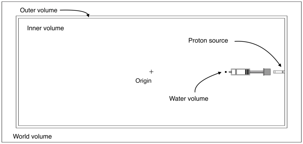
The schematic below shows the Clatterbridge treatment room, illustrating the layout of the geometries defined in DetectorConstruction. The whole beamline is contained within the "inner room" volume, which is placed in the "outer room" volume. As the outer volume is a solid concrete box and the inner volume is a box filled with air, the small overlap models the concrete walls of the treatment room. The proton source is placed against the wall in the inner room (-4200 mm from the origin), and all beamline components are placed relative to this reference point.
Beamline
The positions of the components relative to the source are shown here (annotated PDF). The beamline is shown below. The top figure is a perspective view. The second figure is a top-down view which also shows the borated plastic shielding (f) that was previously hidden to allow the full beamline to be visible.


The beamline consists of the following components:
- an aluminium tube (a) containing from left to right;
- a brass collimator
- a tungsten scattering foil
- a brass beam stopper
- another tungsten scattering foil
- a mylar window
- an empty aluminium box (b)
- an iron block (c)
- a second aluminium tube (d)
- a second aluminium box (e) containing from left to right;
- a brass collimator
- two dose monitors
- cross wires
- a brass nozzle (g)
The water phantom (h) is also shown for completeness.
Dual scattering tube
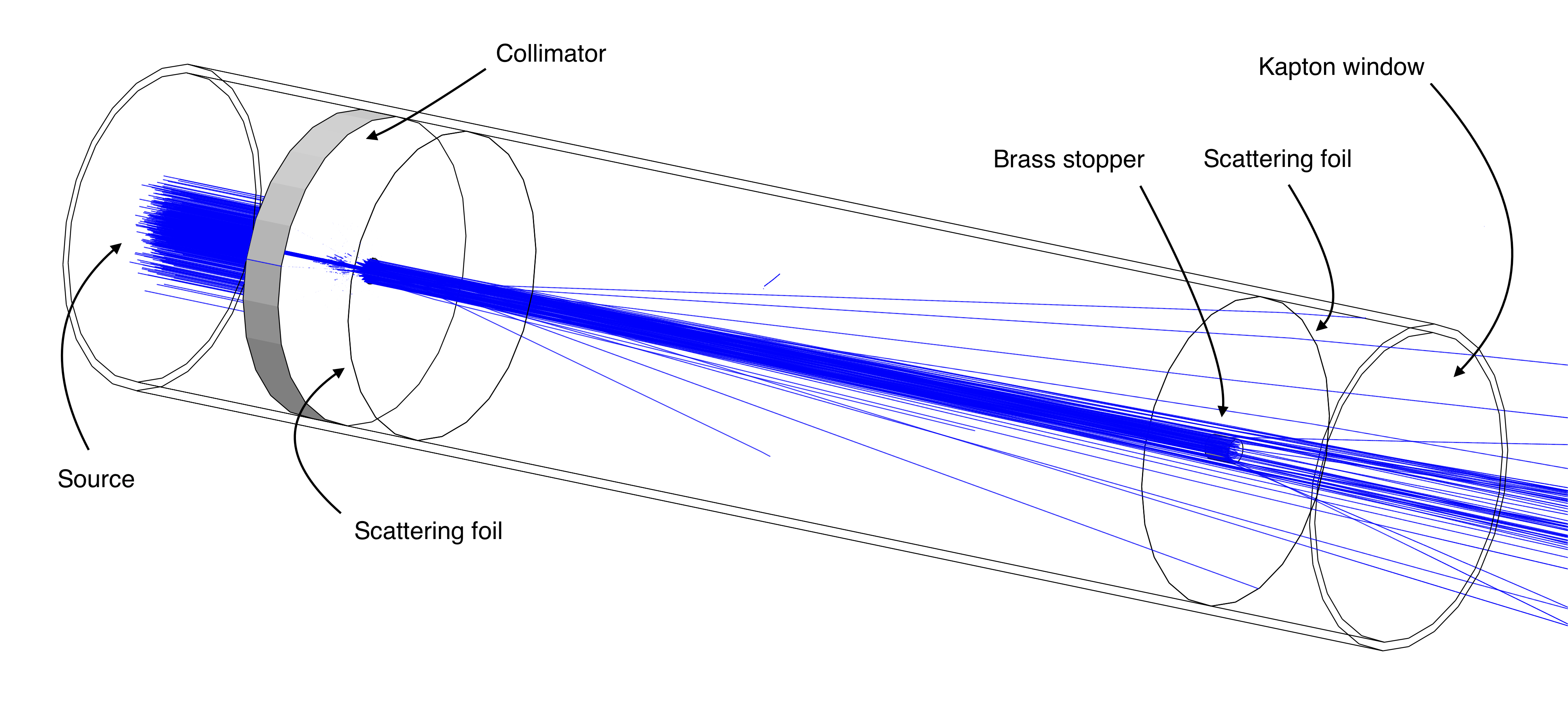
The positions of the components in the tube are shown here (annotated PDF). The proton beam at Clatterbridge is delivered using passive spreading. That is, the beam is spread out using dual scattering where the proton beam is scattered through a first scattering foil followed by a beam stopper and a second scattering foil. The beam stopper is used to reduce the intensity of the beam at its centre and a high-Z material such as tungsten is chosen for the foils as it is highly scattering.
A visualisation of the first tube with 500 primary protons represented by blue tracks is shown below. The protons first travel through the collimator, followed by the first scattering foil which spreads out the beam. The brass stopper then blocks out approximately half of the remaining protons before the beam is again spread out through the second scattering foil. The intention is to produce a wide, homogeneous beam. The particles exit the first tube through a Kapton window which is used to keep the tube under vacuum to reduce random scattering off air molecules.
Dosimetry box
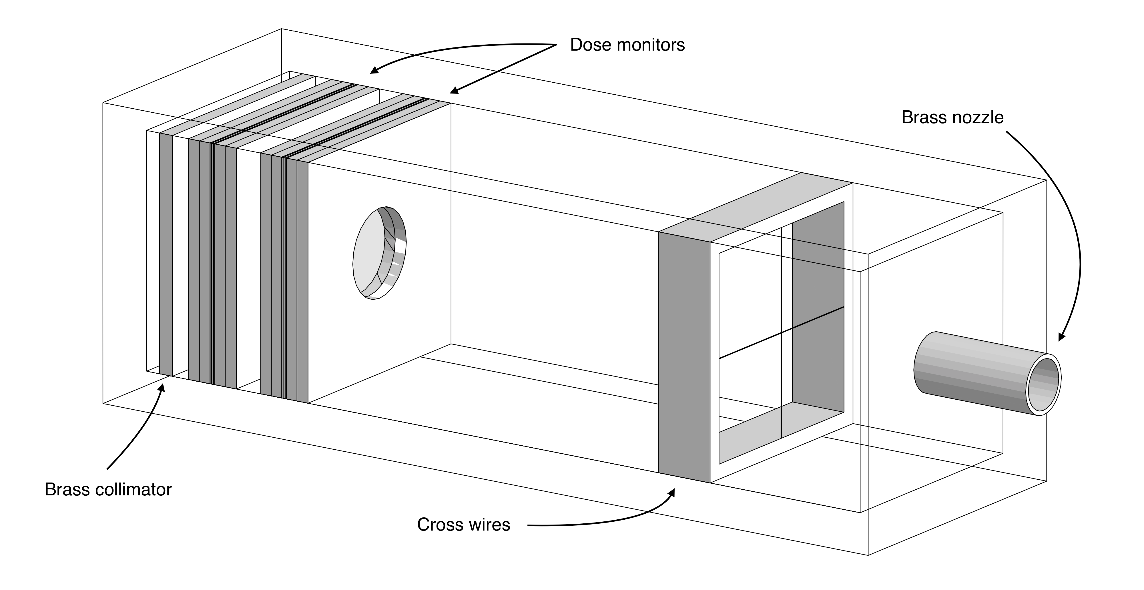
The positions of the components in the dosimetry box are shown here (annotated PDF). The aluminium box shown below contains the dosimetry equipment. The beam is first collimated using a brass collimator to remove any stray protons. The beam then travels through the dose monitors, the cross wires and finally exits the box through the brass nozzle.
Dose monitor
The positions of the components in the dose monitors are shown here (annotated PDF). The dose monitors are drift chambers used to measure the dose deposited by the proton beam. An exploded view of a dose monitor as used in the dosimetry box is shown below. It consists of a set of aluminised mylar foils wedged between layers of perspex to hold them in place. The guard ring is used to create a sealed volume of air between the foils. The aluminium layers face towards the centre of the dose monitor such that the assembly acts as a drift chamber when a potential difference is applied.

Visualisation
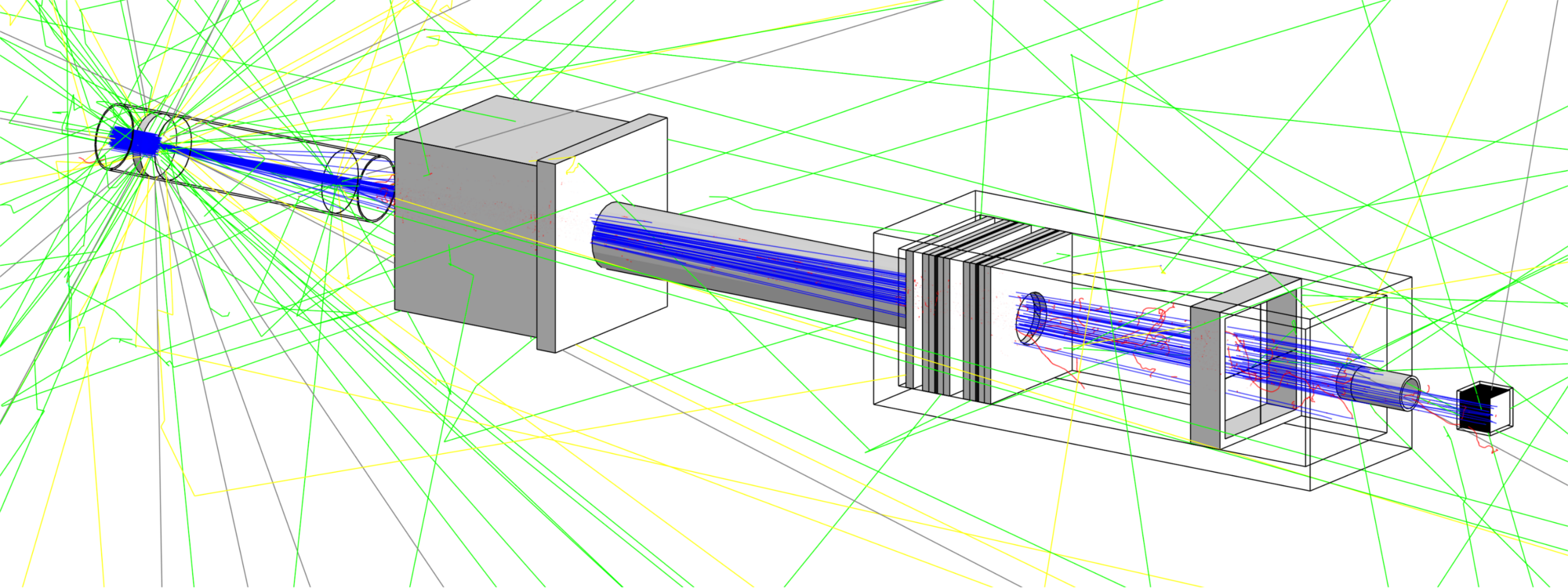
The geometry and particle tracks in Geant4 can be visualised using the DAWN visualiser. Other, perhaps more suitable, visualisers are available (see [1]) but DAWN is useful in that it produces very high-resolution visualisations. The main drawback of DAWN is that it does not allow for click-and-drag functionality. Instead, parameters must be set before each visualisation is drawn which tends to require a fair amount of trial-and-error to obtain good images. All images of the geometry on this page were created using DAWN and an example visualisation of the beamline with all particle tracks drawn can be seen below. The first tube and second box are visualised using the wireframe setting so that their inner components are visible. This example contains 500 primary protons. Protons are shown in blue, electrons are red, positrons are cyan, gamma rays are green, and neutrons are yellow.
Generating primary protons
Using the /gps/ commands
The protons are generated using the G4GeneralParticleSource (GPS) class which allows for a range of properties of the primary protons to be set in the proton.mac file (primaries are the initial particles generated by the GPS). First, the particle source is positioned against the wall on one side of the room which is at -4200 mm from the centre. In an attempt to achieve a more realistic beam, the primary protons are distributed normally in the x and y directions centred at 0 with standard deviations of 4.0 mm and 4.5 mm respectively. This gives the beam width and results in a nearly circular profile. The primaries are generated with initial energies following a Gaussian distribution with mean 62.5 MeV and standard deviation 0.082 MeV, and Gaussian radial distributions with respect to the z-axis with standard deviations of 2.3 mrad and 1.2 mrad in the x and y directions respectively.
The parameters are set in the gps.mac macro as follows:
#-------------------------------------------------------------------------------
# Set particle gun settings
#-------------------------------------------------------------------------------
/gps/particle proton
/gps/number 1 			# per event

# Energy
/gps/ene/type Gauss
/gps/ene/mono 62.5 MeV
/gps/ene/sigma 0.082 MeV

# Source position
/gps/position 0.0 0.0 -4200 mm

# Beam width
/gps/pos/type Beam
/gps/pos/sigma_x 4.0 mm
/gps/pos/sigma_y 4.5 mm

# Angular distribution of primaries for realistic emittance
/gps/ang/type beam2d
/gps/ang/sigma_x 2.3 mrad
/gps/ang/sigma_y 1.2 mrad
/gps/ang/rot1 -1 0 0		# aligns gps with positive z-axis
The macro is called in proton.mac as follows:
#-------------------------------------------------------------------------------
# Primary generator settings
#-------------------------------------------------------------------------------
...
## Use macro to set properties of primaries
/control/execute gps.mac
Reading primaries from a phase space file
Primaries can be generated from an input phase space file using FileReader in PrimaryGeneratorAction. The input must be of the same format as the output files generated by the simulation and its first line is assumed to be a header. The path to the input file should be given in proton.mac and the position at which the particles should be generated:
#-------------------------------------------------------------------------------
# Primary generator settings
#-------------------------------------------------------------------------------
...
## Reading from phase space file
/primarygenerator/input path/to/file

# Set position in z particles are generated at
/primarygenerator/generateAt 0
#/primarygenerator/generateAt 81
#/primarygenerator/generateAt 357
#/primarygenerator/generateAt 1700
Specifying where particles should be generated in useful when running staged simulations as it allows particles to be generated at the same position they were initially recorded at.
Gathering data
Tracking
Accumulating hits over a run
Several quantities can be monitored at different stages in the beamline using the SensitiveDetector defined in PhaseSpaceSD.cc (PhaseSpaceSD extends G4VSensitiveDetector). When a particle hits a boundary on which a PhaseSpaceSD is defined, PhaseSpaceSD::ProcessHits is called and generates a PhaseSpaceHit (extension of G4VHit) that is then stored in the hits collection of the sensitive detector. A unique ID belonging to the volume the hit was registered on is passed to the hit along with any required quantity. Hits are accumulated in the sensitive detector's hits collection over an event (an event corresponds to the full simulation of one primary).
The RunAccumulator (extension of G4Run) accumulates hits over a run (the collection of all events). It is constructed by RunAction::GenerateRun at the start of a run. At the end of an event, RunAccumulator::RecordEvent stores all hits that were registered during the event in the run hits vector and increments the event counter. Once that counter reaches the buffer, the hits are written to their corresponding output file. The buffer size can be set using the following line in proton.mac:
#-------------------------------------------------------------------------------
# Detector settings
#-------------------------------------------------------------------------------
...
# Set buffer size
/user/run/buffer 1000
Recording at regular intervals using a parallel world
To characterise the beam, the evolution of several properties (energy spectrum, emittance, spatial profile, etc.) must be monitored at regular intervals, or at least at several positions, along the beamline. To achieve this, many volumes would need to be defined in DetectorConstruction to be used as sensitive detectors. However, volumes overlapping or sharing boundaries can lead to errors in the simulation and must therefore be avoided. One approach in achieving this would be to carefully construct each detector volume such that it fits in, or around, a given region. An example illustrating why this may be challenging is given by the following; suppose detection was required inside and outside of the first aluminium box on a plane transverse to the direction of the beam. Separate detector volumes would be required on the inside and outside of the box just to detect particles incident on the same plane. This does not yet address the issue of how to handle the boundaries between the box and the detectors as particles would be likely to pass through the gaps and hence go undetected. Even for this simple example, the geometry of the detector volumes would be rather complex and hence not easily reusable.
To avoid these problems, the main geometry (called the mass geometry) can be overlaid with another parallel geometry that does not interact physically with particles in the mass geometry, as described here. Different volumes can then be defined at arbitrary positions and have sensitive detectors assigned to them in ParallelWorldConstruction. To track particles at regular intervals along the beamline, an array of thin boxes is defined by passing the parametrisation ParallelWorldParam (extension of G4VPVParametrisation) to the parametrised volume constructor G4PVParametrised. This creates boxes of a given size at given intervals spanning a given distance from the source. The size of the box can be adjusted in ParallelWorldConstruction, while the spacing and total distance spanned can be set in the proton.mac macro using the following settings:
#-------------------------------------------------------------------------------
# Detector settings
#-------------------------------------------------------------------------------
...
## If using 'all'
/parallel/detector/spacing 25 mm      # default is 25 mm
/parallel/detector/distance 1900 mm   # default is 1900 mm

# Pass spacing and distance to run action and set buffer size
/user/run/detector/spacing 25
/user/run/detector/distance 1900
Recording in a single position (for staged simulations)
Alternatively, particles can be recorded in a single position by choosing one of the components and uncommenting accordingly. The available components are
- scatterfoil1 at 81 mm
- tube1 at 357 mm
- nozzle at 1700 mm
- outside at 1768 m
Components can be added to the components map in ParallelWorldConstruction. Only recording in one position can be useful when the beam has been characterised and the simulation is know to be running as intended. Writing to output less often improves the simulation's performance significantly. This can be used to speed up the simulation further by performing simulations in a staged manner. Sections upstream, where no changes to the geometry are made (e.g. from the source to after the first collimator where the particle count reduces by about 90%), then only need to be simulated once and the output from that simulation can be used as the input to the rest of the simulation.
For example, if the simulation should only run up to the first scatter foil (situated after the first collimator), the commands would look as follows:
#-------------------------------------------------------------------------------
# Detector settings
#-------------------------------------------------------------------------------
...
## Choose where particles are recorded
#/parallel/detector all
/parallel/detector scatterfoil1
#/parallel/detector tube1
#/parallel/detector nozzle
#/parallel/detector outside
...
## If using a component, set dump mode and detector position
/user/run/dump/single true
/user/run/detector/position 81
#/user/run/detector/position 357
#/user/run/detector/position 1700
#/user/run/detector/position 1768

...

#-------------------------------------------------------------------------------
# Stepping action settings
#-------------------------------------------------------------------------------
...
## Kill particles 1 mm after being recorded
/steppingAction/kill 82
#/steppingAction/kill 358
#/steppingAction/kill 1701
#/steppingAction/kill 1769
The command /user/run/dump/single sets a flag used in RunAccumulator::InitialiseOutputFiles.
Scoring
Scorers are defined in score_init.mac and the quantities they record are dumped to files as defined in score_dump.mac.
Longitudinal scoring mesh
A scoring mesh is longitudinal in the sense that it records data along the direction of the beamline, e.g. the energy deposited at different positions in z. Hence, for a mesh to be longitudinal it must have bins defined along its z-axis. The scorer defined on the mesh detEnergyLon is an example of such a mesh. It is defined as follows:
/score/create/boxMesh detEnergyLon
/score/mesh/boxSize 20. 20. 20. mm
/score/mesh/nBin 1 1 200
/score/mesh/translate/xyz 0. 0. -2340 mm
/score/quantity/energyDeposit energyDeposit
/score/close
On the third line in the snippet above you can see that there is only a single bin in both the x and y directions but 200 in the z-direction.
Lateral scoring mesh
Similarly to the longitudinal meshes, a mesh is said to be lateral when it records data transverse to the direction of travel of the protons. For a mesh to be lateral it must have bins defined perpendicularly to its z-axis. The scorer defined on the mesh braggEnergyLat is an example of such a mesh. It is defined as follows:
/score/create/boxMesh braggEnergyLat
/score/mesh/boxSize 20. 20. 0.5 mm
/score/mesh/nBin 200 1 1
/score/mesh/translate/xyz 0. 0. -2329.2 mm
/score/quantity/energyDeposit energyDeposit
/score/close
Again, you can see that there is only a single bin in the y and z directions but 200 in the x-direction.
Running simulations
Build the simulation
To access a Linux desktop PC running Scientific Linux 6, follow the instructions here. Once access has been established, follow the instructions below to copy the simulation files to your directory:
[username@pc1XX ~]$ mkdir sim
[username@pc1XX ~]$ cd sim
[username@pc1XX sim]$ cp -r /unix/pbt/users/mhentz/Clatterbridge_sim/source .
[username@pc1XX sim]$ mkdir build
[username@pc1XX sim]$ cd build
[username@pc1XX build]$ /unix/pbt/software/scripts/pbt.sh
[username@pc1XX build]$ cmake -DGeant4_DIR=/unix/pbt/software/dev ../source
[username@pc1XX build]$ make -j4
Running the simulation in batch mode with macro
This will run the simulation and produce the required output files in the data subdirectory created.
[username@pc1XX build]$ mkdir data
[username@pc1XX build]$ ./clatterbridgeSim proton.mac
Running simulations in parallel
A simulation comprising of a large number of particles can take a long time to run as events run sequentially (about 20 hours for 1e6 events). This can be reduced considerably by running a number of independent simulations with fewer events "in parallel" and then merging the output files once they have completed. The main limitation lies in the maximum number of simulations that can be run simultaneously–which is 120. Splitting 1e6 events into 100 simulations of 10,000 events reduces the runtime to a much more bearable 20 minutes.
For parallel simulations, some parameters need to be set in the macro proton.mac.
- When running simulations in parallel, each simulation is executed two directories further down from where the parallel run is initialised. Hence, the correct path to the
gps.macmacro should be set inproton.mac:
#-------------------------------------------------------------------------------
# Primary generator settings
#-------------------------------------------------------------------------------
...
# Parallel version
/control/execute ../../gps.mac
- Separate simulations should have different random number generator seeds so that they are independent but in order for simulations to be reproducible, the same sequence of seeds should be assigned for each run. To achieve this, the seeds in
proton.macare set by the job submission scriptcb_parallel.shusing the index of the current simulation. For theproton.macmacro to use the seeds set by the submission script, the following line should be set:
#-------------------------------------------------------------------------------
# Set seeds for randon number generators
#-------------------------------------------------------------------------------
...
# Parallel version
/random/setSeeds ${seed1} ${seed2}
- If generating primaries from a phase space file that was split using
split_input.shas described below, the number of events is set bycb_parallel.shinproton.macand the following line should be uncommented:
#-------------------------------------------------------------------------------
# Run simulation
#-------------------------------------------------------------------------------
...
# Parallel version with split input file
/run/beamOn ${nevents}
As mentioned above, simulations can be run in parallel while reading primaries from an input file. This file should be split and distributed evenly across the simulations using split_input.sh in order to make use of the parallelism. The script calculates the number of lines each simulation should receive given a number of simulations and then writes chunks of the initial file to separate files which will then be used as input files for the parallel simulation. It should be called in the simulation's base directory as follows:
./split_input.sh /path/to/file nsimulations
The script run.sh (located in the source directory but should automatically be copied to build by cmake) creates a timestamped directory along with a few useful subdirectories and submits a specified number of simulations to be executed there. It is currently set to submit 100 jobs to the medium queue through the submit.sh script. This can be changed by supplying different arguments on line 22 (other queues available are short and long):
../submit.sh 100 medium
The script submit.sh assigns values to the variables in the template clatterbridge_split.sh and writes the result to a job submission script clatterbridge_X.sh for all 100 simulations. This is done on line 31:
cat ../clatterbridge_split.sh | sed -e "s/\${i}/$i/" >> clatterbridge_$i.sh
Besides setting vital parameters and navigating to the correct folder, the submission script sets the seeds in proton.mac_split and writes the result to a new macro proton.mac_simX. It then runs the simulation with the corresponding macro.
Follow the instructions in "Make the simulation " unless you have already done so. Split simulations are run as follows:
[username@pc1XX build]$ ./run.sh
Monitoring job status
The status of the simulations can be tracked with the following command (can be used in conjunction with the watch command):
[username@pc1XX build]$ qstat -u <username>
If something goes wrong and you wish to stop all the jobs simultaneously you can use the command
[username@pc1XX build]$ qselect -u <username> | xargs qdel
The resulting data can be combined by running the scripts combine_tracking.py and combine_scorers.py as follows:
[username@pc1XX build]$ cd timestamp-dir
[username@pc1XX timestamp-dir]$ cp ../../source/combine_*.py .
[username@pc1XX timestamp-dir]$ ./combine_tracking.py
[username@pc1XX timestamp-dir]$ ./combine_scorers.py
Output files
Output used for beam emittance and energy spectra
The output files output_zX.txt are written to the subdirectory data/ in SteppingAction.cc (X is the position in z where the protons were recorded). Other particles can be recorded by changing SteppingAction.cc accordingly. The output files contain the parent ID which is 0 for a primary particle and non-zero for all other particles, the xyz-coordinates in mm, the angle subtended by the projection of the momentum vector onto the x-axis and the z-axis in mrad (used to plot the beam emittance) and the kinetic energy in MeV. The z-coordinates are given relative to the position of the particle source and the z-axis lies along the beamline with its positive end pointing towards the origin. An example is shown below (output_z1759.txt):
# zposition: 1759
# parentID, x, y, z [mm], theta [mrad], ke [MeV]
0 -9.78358 4.39357 1759.0 -6.01461 60.32370
0 -7.12684 -10.49640 1758.9 -4.95641 60.12080
0 8.83137 -2.33413 1759.0 10.60610 60.07960
0 5.92333 -3.29109 1758.9 7.89279 60.20930
0 -2.21463 6.24370 1759.0 -6.14550 60.04930
...
Scorer outputs
The files described below are all written using the /score/dumpQuantityToFile commands in score_dump.mac. The data are recorded by the scorers defined in score_init.mac.
Lateral energy deposition at the Bragg peak in the detector
The file BraggEnergyDepLat.txt contains data recorded by the energyDeposit scorer defined on the braggEnergyLat mesh in score_init.mac. It records the energy deposition at the Bragg peak in the plane perpendicular to the direction of incidence of the beam. The columns represent the bin number in the x, y and z directions and the energy deposition in MeV (as the mesh is only binned in x, it consists of strips parallel to the y-axis):
# mesh name: braggEnergyLat
# primitive scorer name: energyDeposit
# iX, iY, iZ, value [MeV]
0,0,0,29.931796279684590
1,0,0,38.256791245912446
2,0,0,115.051837974658625
3,0,0,185.831154261095321
...
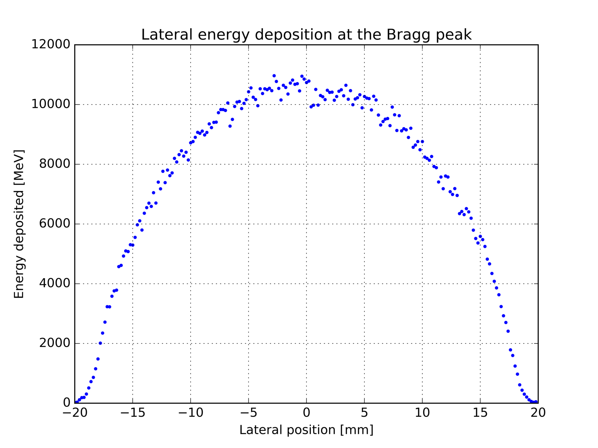
This file can be used to plot the lateral energy deposition profile at the Bragg peak.
Longitudinal energy deposition throughout the detector
The file DetEnergyDepLon.txt contains data recorded by the energyDeposit scorer defined on the detEnergyLon mesh in score_init.mac. It records the energy deposition in the detector in bins along the beam. The columns represent the bin number in the x, y and z directions and the energy deposition in MeV:
# mesh name: detEnergyLon
# primitive scorer name: energyDeposit
# iX, iY, iZ, value [MeV]
0,0,0,59390.147050145809771
0,0,1,59016.142052385039278
0,0,2,59209.373600437116693
0,0,3,59578.920521325460868
...
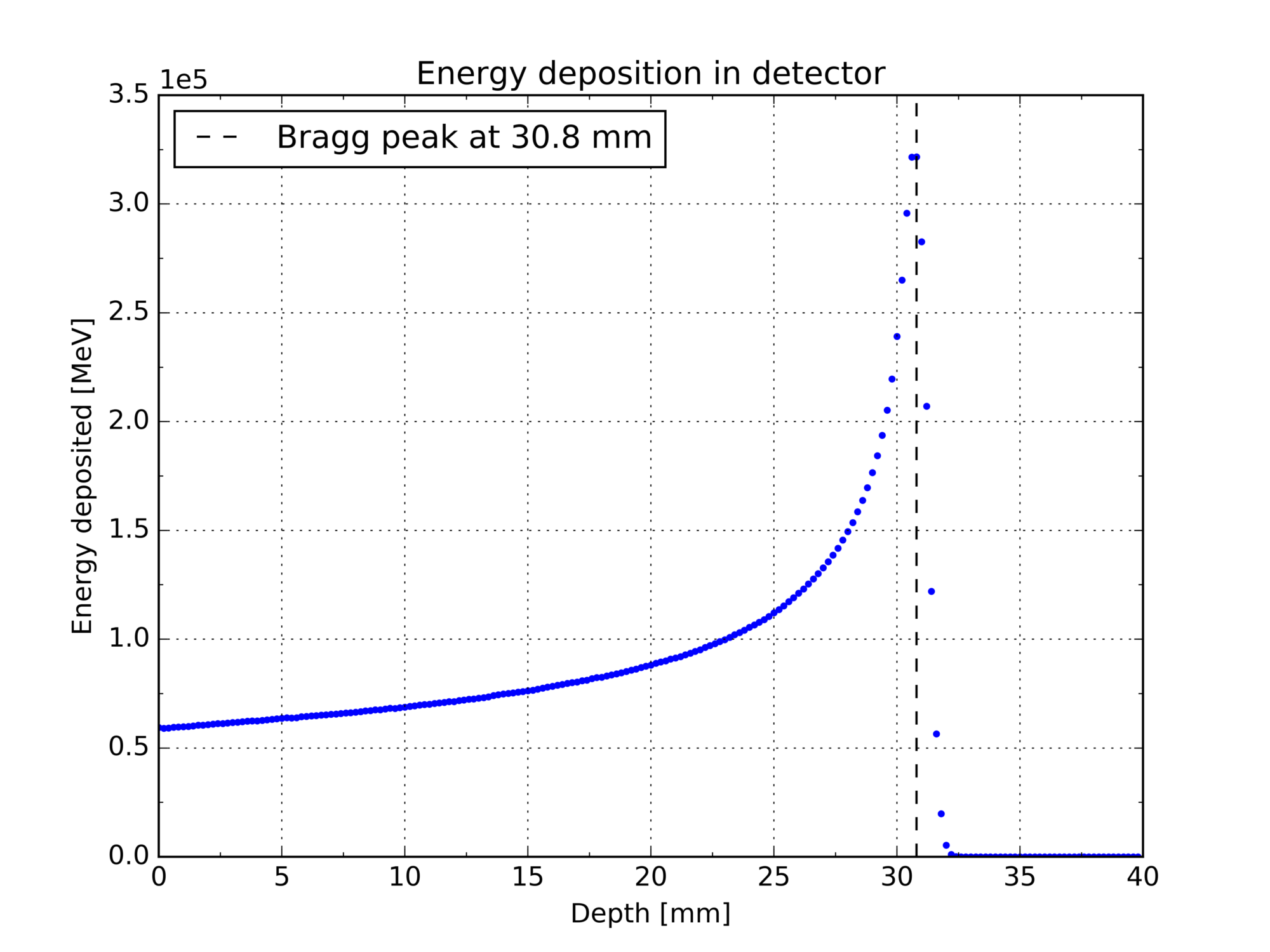
This file can be used to plot the energy deposition profile through the detector. The Bragg peak can be identified from such a plot.
Data Analysis
Beam profile, emittance and energy spectrum
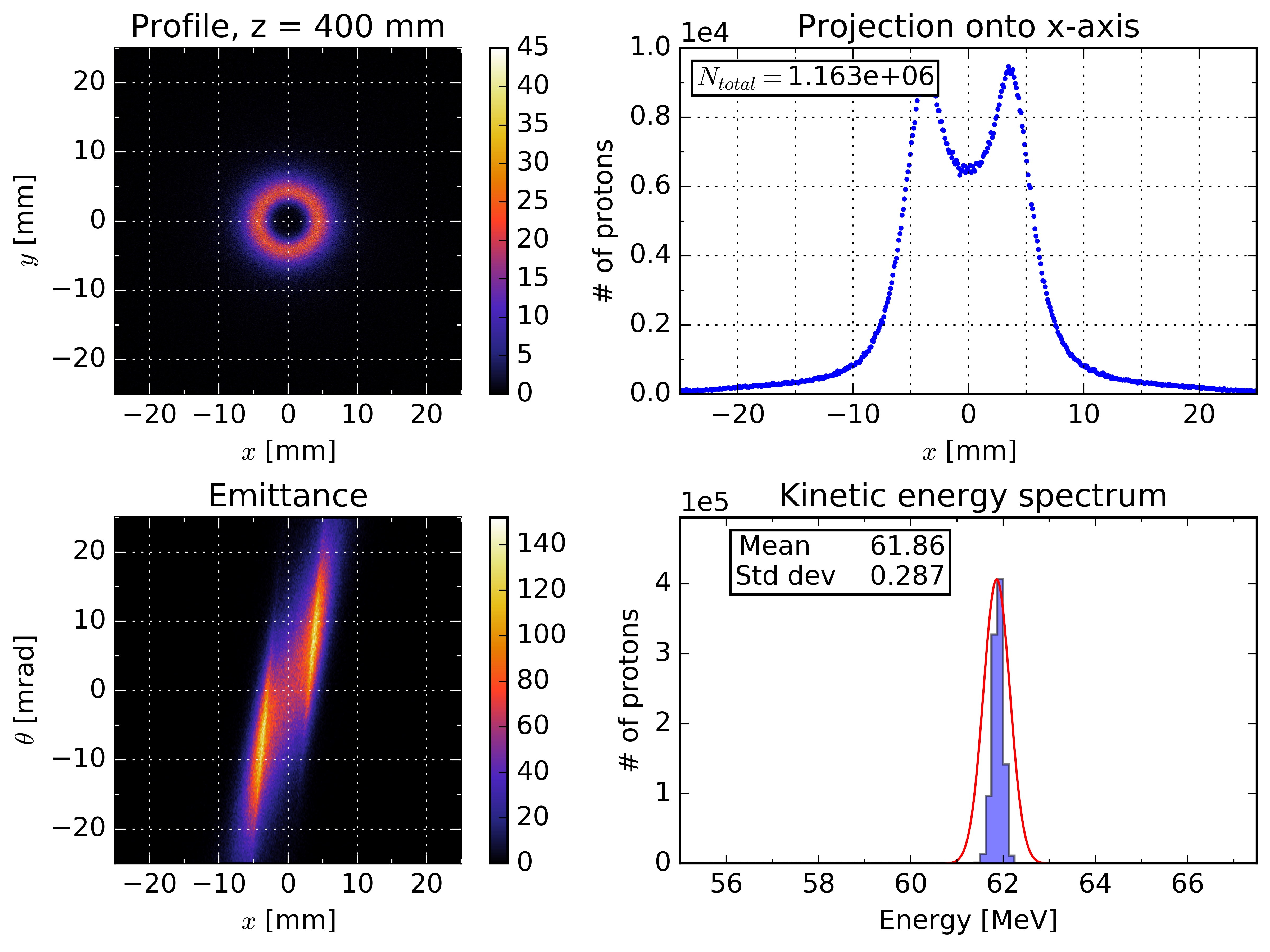
The script analysis.py produces several different plots from the output_zX.txt files. It plots the beam profile, the projection of the beam profile onto the x-axis, the beam emittance and the energy spectrum at the position in z where the protons were recorded. This script requires the SciPy module which is not available on the Linux SL6 PCs. Hence, it must currently be run locally. It is run for a given position along the beamline as follows (400 mm as an example, the script must be run in the directory containing the data subdirectory):
[user@hostname ~]$ ./analysis.py 400
This runs the script using the file output_z400.txt and produces the corresponding plots shown below. At this stage, the beam has undergone dual scattering and is starting to spread out again to produce a uniform beam.
Longitudinal energy deposition profile and Bragg peak
The script bragg.py plots the longitudinal energy deposition profile through the detector from DetEnergyDepLon.txt. It is executed using Python 2.7 in the same directory as the data file as follows:
[user@hostname ~]$ ./bragg.py
This produces the following plot;
Lateral energy deposition profile at the Bragg peak
The script lateral.py plots the lateral energy deposition at the Bragg peak from BraggEnergyDepLat.txt described above. It is executed on Python 2.7 as follows:
[user@hostname ~]$ ./lateral.py BraggEnergyDepLat.txt
This produces the following plot;
Changing parameters
Beam parameters
These can be modified in proton.mac under the header "particle gun settings".
Energy
The GPS gives the initial protons a range of energies following a Gaussian distribution.
/gps/ene/type Gauss
/gps/ene/mono 62.5 MeV
/gps/ene/sigma 0.082 MeV
Source position
The proton source is positioned at z = -4200 mm relative to the centre of the inner room, which corresponds to a position against the wall of the inner room.
/gps/position 0.0 0.0 -4200 mm
Scoring meshes
Filters can be applied to scoring meshes so as to only record a given type of particle using the command /score/filter/particle protonFilter proton in the definition of the scoring mesh. This can be useful as, for example, one may want to monitor the flux of different particles along the beamline. This would require a large mesh positioned over the whole beamline as follows:
/score/create/boxMesh beamlineLongitudinal
/score/mesh/boxSize 50. 50. 1000. mm
/score/mesh/nBin 1 1 400
/score/mesh/translate/xyz 0. 0. -3200 mm
/score/quantity/flatSurfaceFlux protonFlux
/score/filter/particle protonFilter proton
/score/quantity/flatSurfaceFlux neutronFlux
/score/filter/particle neutronFilter neutron
/score/close
This mesh records two separate quantities, the proton flux and the neutron flux, which can then be written to separate output files.
Beamline components
Components of the beamline can be added, removed or modified in DetectorConstruction.cc. For example, the position of the second dose monitor can be changed by changing the z-value of the G4ThreeVector on the line below. As the dose monitor is placed within the dosimetry box lAlBox2 it's position is given relative to the centre of that box.
pDoseMonitor2 = new G4PVPlacement(0, G4ThreeVector(0, 0, -169.5*CLHEP::mm), lDoseMonitor1, "DoseMonitor2", lAlBox2, false, 0, checkOverlaps);
After any changes made to the source or header files (ending in .cc or .hh), the code will need to be recompiled. In the build directory, write:
[username@pc1XX build]$ make
Physics list
A user-defined physics list can be specified in PhysicsList.cc and then selected in clatterbridgeSim.cc using the line
runManager->SetUserInitialization(new PhysicsList);
Tracking positions
As described in the section "Tracking ", protons are tracked in SteppingAction.cc. This class contains a vector trackingPosVec which contains the positions of interest where protons are to be tracked. Positions can be changed by changing trackingPosFiller in the header file SteppingAction.hh on the following line:
trackingPosFiller = { 0, 45, 79, 81, 100, 150, ..., 1759, 1800, 1839, 1881 };
Don't forget to recompile after any changes made.