Clatterbridge: Difference between revisions
m (→Files) |
m (→Files) |
||
| Line 347: | Line 347: | ||
== Files == | == Files == | ||
[[ | [[Clatterbridge files|List of files for Clatterbridge simulation]]. | ||
Revision as of 14:42, 27 September 2016
Simulation of the Clatterbridge beamline
This simulation models the monoenergetic 62.5 MeV proton beam at Clatterbridge Cancer Centre, as it traverses the components of the beamline and is then deposited into a volume of water. The beamline components are contained within a geometry modelling the Clatterbridge treatment room.
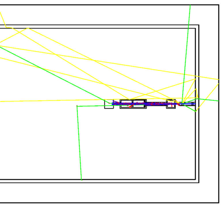
The protons are generated using the G4ParticleGun class, and the physics list used is QGSP_BIC_HP, standard for simulating clinical proton beams.
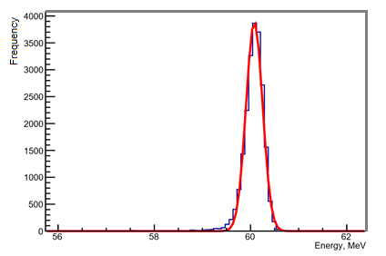
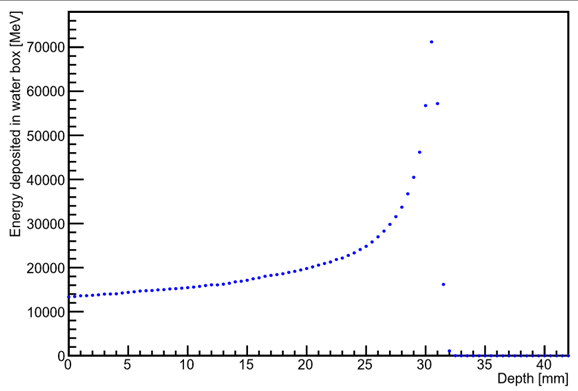
The energy of the beam after travelling through the beamline components is measured by tracking the energy deposition of individual protons within the water volume, using an implementation of the G4VSensitiveDetector.cc class. This simulation produces a post-beamline energy of 60.08 MeV and a Bragg peak at a depth of 31 mm in water.
The figure to the right shows the visualisation output of the simulation, displaying the particle tracks. Protons are shown in blue, electrons in red, gammas in green and neutrons in yellow.
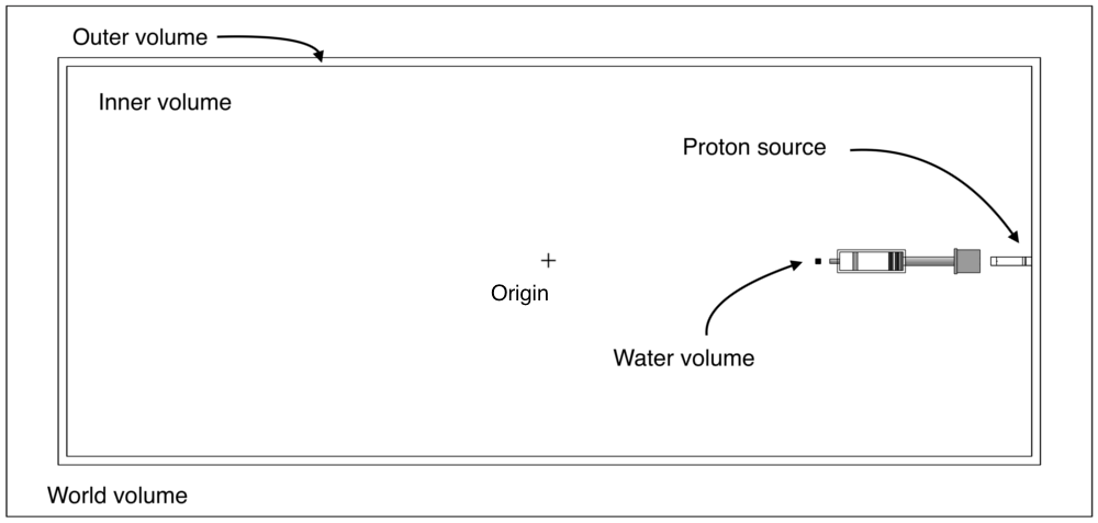
Below shows a schematic of the Clatterbridge treatment room, illustrating the layout of the simulated geometries. All beamline components have been created within the "inner room" volume, which in turn was created within the "outer room" volume, to simulate the marble walls. The proton source is located at the air/wall boundary within the inner room, and all beamline components were placed relative to this reference point.
Running the simulation
Run macro proton.mac
This will run the simulation and produce the required output files.
[username@plus1 ProtonPB_build]$ ./protonPB proton.mac
Output files
The simulation code and proton.mac produce several output files:
protonKE.out
This text file contains output information from SteppingAction.cc , printed on a step-by-step basis for each proton (event). The first two columns contain the x and y coordinates (in mm) of the proton. The third column contains the z position of the proton (in mm), relative to the position of the source at the inner room boundary. The last column contains the energy (MeV) of the proton at this z position.
 6.66882  -11.4767  1770  59.8738
-7.60842  -11.4391  1770  60.186
-9.37841  -14.363   1770  43.1861
-13.2143   1.55943  1770  60.4776
 1.81337   11.558   1770  60.2989
secondariesKE.out
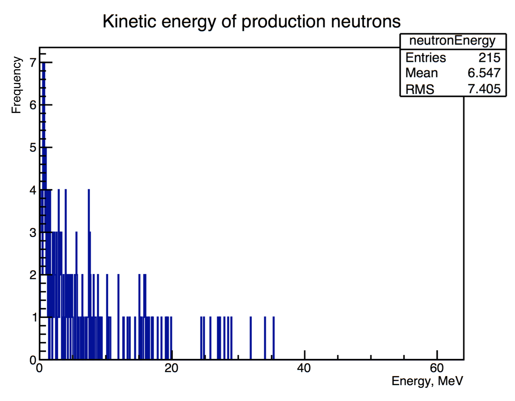
This text file contains information recorded in SteppingAction.cc about neutrons produced in the simulation. The values shown in the file are the kinetic energies [MeV] of the neutrons produced within the specified volume in the code.
5.12058
2.71641
sensitiveDetectors.out
This file contains the ID of the sensitive detector (first column) and the energy deposited in that detector (second column). The ID number "0" corresponds to the water volume sensitive detector, and ID number "1" corresponds to the user-defined sensitive detector.
1	62.2594
0	43.1061
1	0
0	0
1	62.2851
ProtonFluxBeamline.txt
This file is automatically written by proton.mac and contains the proton flux data from the longitudinal scorer. The columns represent the bin number in the x, y and z directions, and the number of protons per cm2:
# mesh name: waterMeshlongitudinal
# primitive scorer name: protonFlux
# iX, iY, iZ, value [percm2]
0,0,0,25.97935669321147
0,0,1,25.90015344712939
0,0,2,25.84461190407653
In simulation_analysis.C the data in ProtonFluxBeamline.txt is read in and written to another text file, ProtonFluxBeamline_Mod.txt to modify the standard formatting into a suitable format for further analysis:
0 0 0 25.97935669321147
0 0 1 25.90015344712939
0 0 2 25.84461190407653
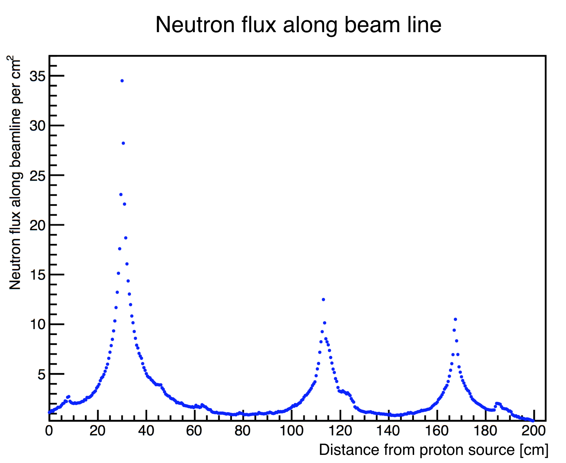
A similar output file, NeutronFluxBeamline.txt is produced in the simulation, and contains information about the flux of neutrons along the entire length of the beamline.
An additional two text files are produced from another longitudinal scoring mesh, located specifically along the length of the water volume. ProtonFluxWaterLongitudinal.txt contains information about the proton flux within the water volume, and ProtonEnergyWaterLongitudinal.txt contains information on the cumulative energy deposition of the proton beam within the water volume.
ProtonEnergyWaterLongitudinal.txt
This text file is produced by proton.mac in the same way as ProtonFluxBeamline.txt above, and contains information about the proton energy deposited within the water volume, divided into bins parallel to the beam:
# mesh name: waterMeshlongitudinal
# primitive scorer name: energyDeposit
# iX, iY, iZ, value [MeV]
0,0,0,14778.66421571247
0,0,1,14787.50686991539
0,0,2,14943.0041959171
EnergyLateralMesh.txt
This text file is produced by proton.mac in the same way as the other scorers above, and contains information about the proton energy deposition in bins perpendicular to the beam:
# mesh name: waterMeshlateral
# primitive scorer name: energyDeposit
# iX, iY, iZ, value [MeV]
0,0,0,0
1,0,0,0

...

16,0,0,0.002151585502782383
17,0,0,0.01565800625140965
18,0,0,9.09434626226223
19,0,0,0.01811169052807143
Data Analysis
Open ROOT and run analysis file
The simulation analysis file reads the data in the output files and produces the associated plots.
[username@plus1 ProtonPB_build]$ root -l

root [0] .x simulation_analysis.C
Proton energy deposition in water
On the left is a histogram showing the frequency of incident protons to the water box at different energy values. It is produced from data in stopper.txt which contains the hits data from the sensitive detectors in the simulation, including the water volume sensitive detector which is used here. The peak in proton energy deposited in the water volume is found to be at 60.08 MeV.
The plot on the right shows the cumulative proton energy deposited within the water volume, plotting data collected in the longitudinal water volume scoring mesh, showing the Bragg peak at 31 mm.
Proton stopping distance in water
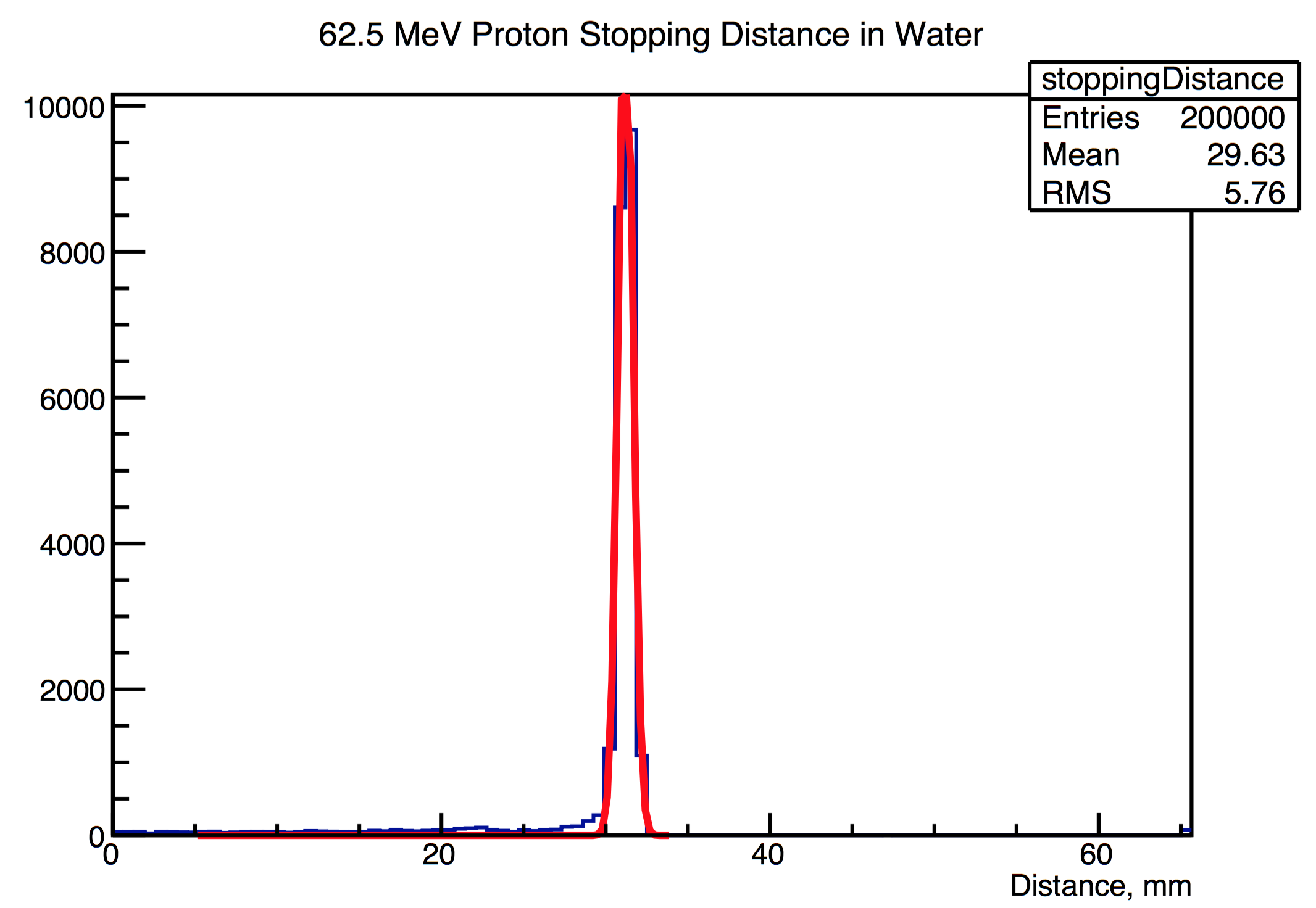
This plot shows the stopping distance of protons in the water volume, with the stopping distance defined as the point at which the velocity of the protons is zero.
Proton flux along beamline
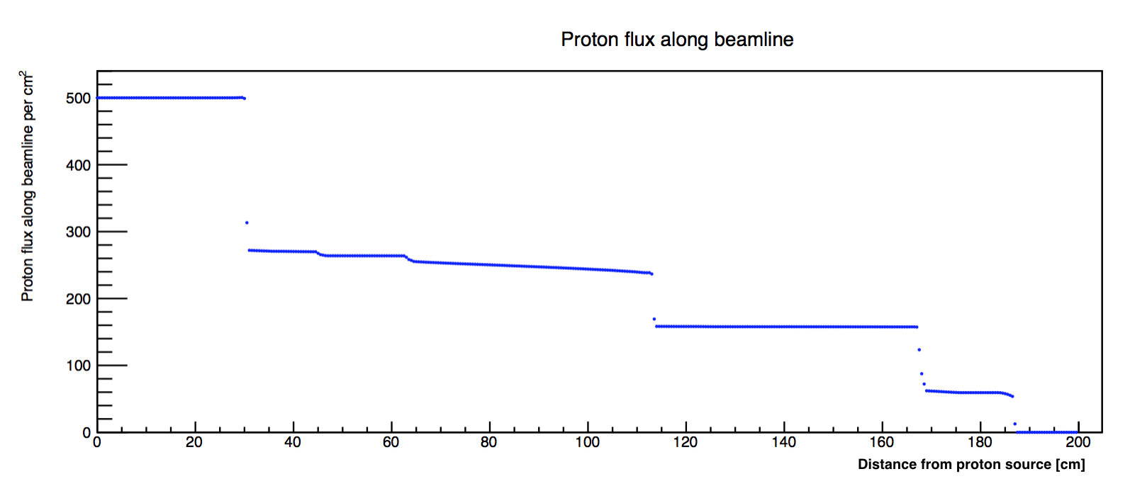
This plot is produced from FluxLongitudinal_Mod.txt and shows the number of protons per cm2 passing through distinct points along the beamline (in the z direction). The decrease in proton flux is clearly shown at particular points along the beamline, for example at the location of the brass stopper (30cm).
Proton flux along water volume
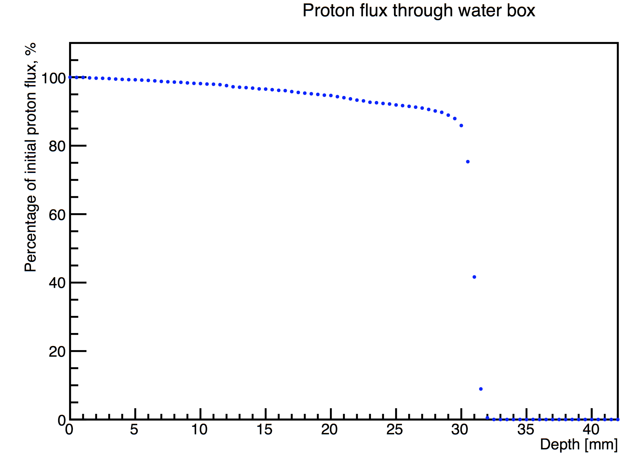
Using a similar setup as the previous beamline flux plot, proton flux data from the scoring mesh within the water volume was plotted.
Kinetic energy of the proton beam
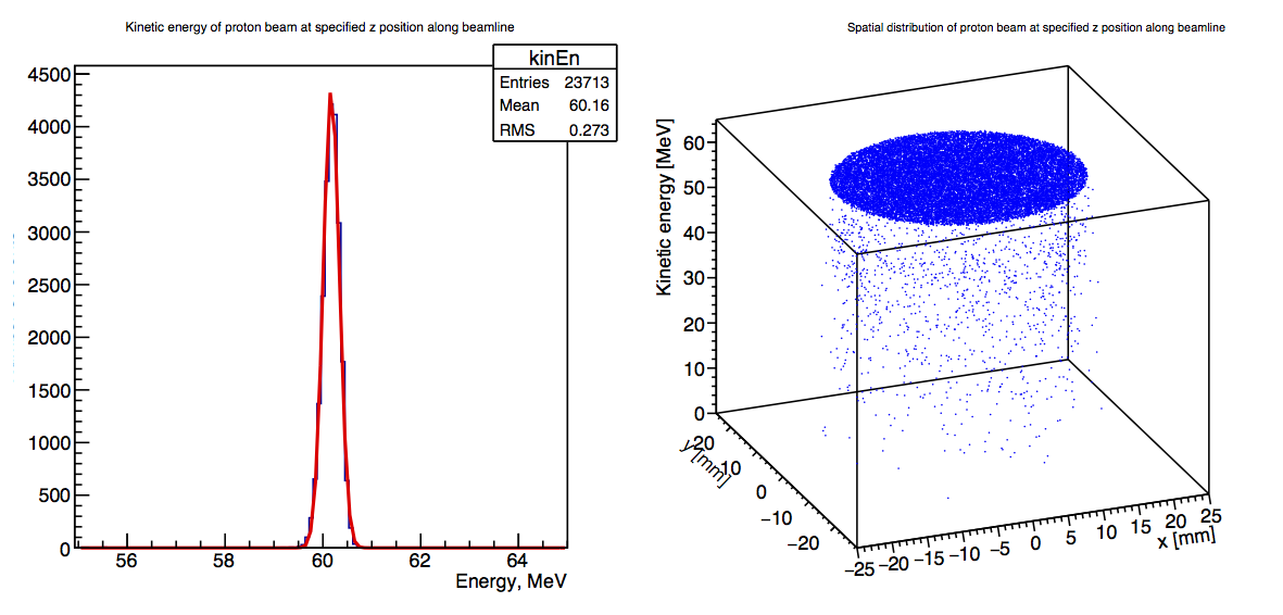
This left-hand plot is produced from kin.out and shows the kinetic energy distribution of the proton beam at a specified point along the beamline. This location is specified in SteppingAction.cc in which a particular position in z can be input (see Section 5.6 Kinetic Energy Readings).
The xy coordinates of each proton are also recorded, and are used to produce a plot which shows the spatial coordinates and the kinetic energy of each proton at the specified position in z, along the beamline.
Neutron production
Neutron flux along beamline
Neutron kinetic energy
Data on the energy of neutrons produced within a particular volume along the beamline was collected, with the volume specified in SteppingAction.cc - the plot below shows the energy of neutrons produced within the water volume.
Changing parameters
Initial beam parameters
Initial parameters of the proton beam can be modified in proton.mac
Beam radius
/gps/pos/radius 3 mm
Beam energy
This simulation models the proton beam source with a Gaussian distribution.
/gps/ene/type Gauss
/gps/ene/mono 62.5 MeV
/gps/ene/sigma 0.082 MeV
Source position
The proton source is positioned at z = -420 cm relative to the centre of the inner room (the mother volume), which translates as the wall surface of the inner room.
/gps/pos/type Plane
/gps/pos/shape Circle
/gps/pos/centre 0.0 0.0 -420 cm
Scoring mesh
Longitudinal scoring mesh
A longitudinal scoring mesh extends along the length of the beamline from the source to the water volume. The mesh utilises a filter to detect the flux of protons per cm2 and writes the data to the text file FluxLongitudinal.txt . The location of the mesh centre can be changed in proton.mac , in addition to the dimensions of the mesh and the number of bins.
/score/create/boxMesh waterMeshlongitudinal
/score/mesh/boxSize 10. 10. 10. cm
/score/mesh/nBin 1 1 400
/score/mesh/translate/xyz 0. 0. -226 cm
The filter can also be changed to observe the flux of particles other than protons:
/score/quantity/cellFlux protonFlux
/score/filter/particle protonFilter proton
Lateral scoring mesh
A lateral scoring mesh is positioned at the end of the nozzle to record the dose distribution of the protons. The position, size and bin number of this mesh can be modified in the same way as the longitudinal mesh example above.
Beamline components
Components of the beamline can be added/removed in DetectorConstruction.cc . If the dimensions of the water box are modified, the following lines in simulation_analysis.C will also need to be modified:
Float_t lengthBox = 200, widthBox = 200;
The depthFix variable to calculate the stopping distance of the protons within the analysis will also need to be adjusted if the water box dimensions or location are modified. depthFix is calculated by taking the z position of the centre of the water box (relative to the centre of the inner room), and subtracting the half length of the water box (calculated in mm):
//depth fix - water box centred at -2260 mm, half length = 100 mm.
Double_t depthFix = 2360;
Sensitive detectors
In this simulation, the water volume is assigned as a sensitive detector in DetectorConstruction.cc :
G4SDManager* SDman = G4SDManager::GetSDMpointer();
G4String name="SD";
DetectorSD = new SensitiveDetector(name);
SDman->AddNewDetector(DetectorSD);
logicWater->SetSensitiveDetector(DetectorSD);
Another beamline component may be used by modifying the following line and setting its logical volume as a sensitive detector:
logicWater->SetSensitiveDetector(DetectorSD);
The component should be chosen such that a significant proportion of the proton beam deposits energy, such as in the brass stopper, in order to produce enough data for plots.
SensitiveDetector.cc is derived from the G4VSensitiveDetector.cc base class. On a step-by-step basis, the energy deposited by the proton is recorded as a "hit" and added to a HitsCollection object. Other parameters may be retrieved at each step in the method ProcessHits .
G4bool SensitiveDetector::ProcessHits(G4Step* aStep, G4TouchableHistory* ROhist)
{
  G4double edep = aStep->GetTotalEnergyDeposit();
  if(aStep->GetTrack()->GetDefinition()->GetParticleName() == "proton"){
    ::Hit* newHit = new ::Hit();
    newHit->SetEdep(edep);
    HitID = detectorCollection->insert(newHit);
    return true;
  }
Physics list
This simulation uses one of the standard physics lists: QGSP_BIC_HP. A user-defined physics list can be specified in the class PhysicsList.cc .
Kinetic energy readings
[could go under data analysis section]
The kinetic energy of the beam after passing through a particular component of the beamline is found in the class SteppingAction.cc . This class contains a map named componentMap with the names of the components as keys and the z coordinate of each component (taken as the furthest edge from the source):
componentMap.insert( std::pair<std::string,double>("ScatteringFoil1",80.025));
componentMap.insert( std::pair<std::string,double>("BrassStopper",306.6));
componentMap.insert( std::pair<std::string,double>("ScatteringFoil2",306.625));
To find the kinetic energy distribution of the beam at a particular point, insert the component name from the map above into this line:
double cPos = (double)componentMap.find("ScatteringFoil2")->second;
The code then compares the z position of a proton with the position of the chosen component on a step-by-step basis, and if the proton is at the chosen position its kinetic energy is recorded in kin.out :
if(fabs(zpos-cPos) < 1.0e-8){
   std::ofstream hitsfile(filename, std::ios::app);
   if(hitsfile.is_open()){
      G4double ke =  step->GetPreStepPoint()->GetKineticEnergy();
      hitsfile << zpos << "\t"
	       << ke <<G4endl;
      hitsfile.close();
   }
}
After any modifications to the simulation files, the code will need to be compiled. In the build directory, write:
[username@plus1 ProtonPB_build]$ make
After this proton.mac can be run:
[username@plus1 ProtonPB_build]$ ./protonPB proton.mac
Modifying Analysis Methods
The number of bins to store the data for each histogram can be changed, here the number of bins is 800:
TH1D* waterEnergy = new TH1D ("waterDep", "Energy deposition in water box", 800, 0., 65.);
The range of the axes for each plot can also be specified in order to zoom into the energy peak:
waterEnergy->GetXaxis()->SetRangeUser(0, 64);
